Tire manipulator

Active Publication Date: 2019-06-27
CYNERGY ERGONOMICS INC
View PDF13 Cites 6 Cited by
  • Summary
  • Abstract
  • Description
  • Claims
  • Application Information

AI Technical Summary

Benefits of technology

[0011]The present invention overcomes the stated deficits in the prior art and provides for an improved tire manipulator that is easier and more comfortable to use. In one embodiment, the present invention is directed to a suspended tire manipulator for use by an operator in lifting a tire having a mounting aperture. The manipulator comprises a first handle and a second handle. T

Problems solved by technology

Such tasks present a risk of injury not just to the employees directly involved in the relocation task, but to other employees in the vicinity of the involved employees.
In addition, moving bulky objects in the workplace requires dedication of man-power and time resources, which add operating costs t

Method used


Image

  • Tire manipulator
  • Tire manipulator
  • Tire manipulator

Examples


Embodiment Construction

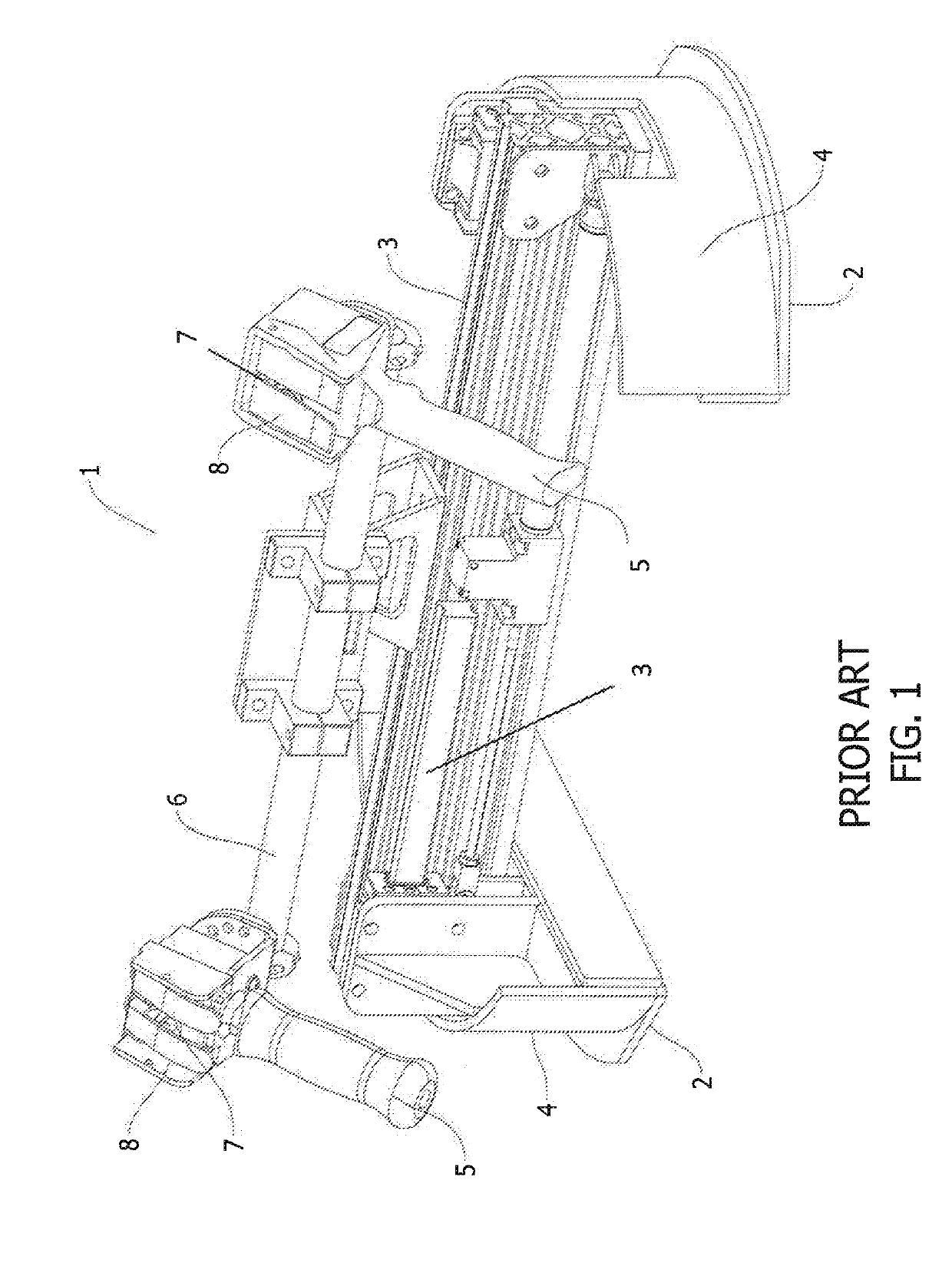
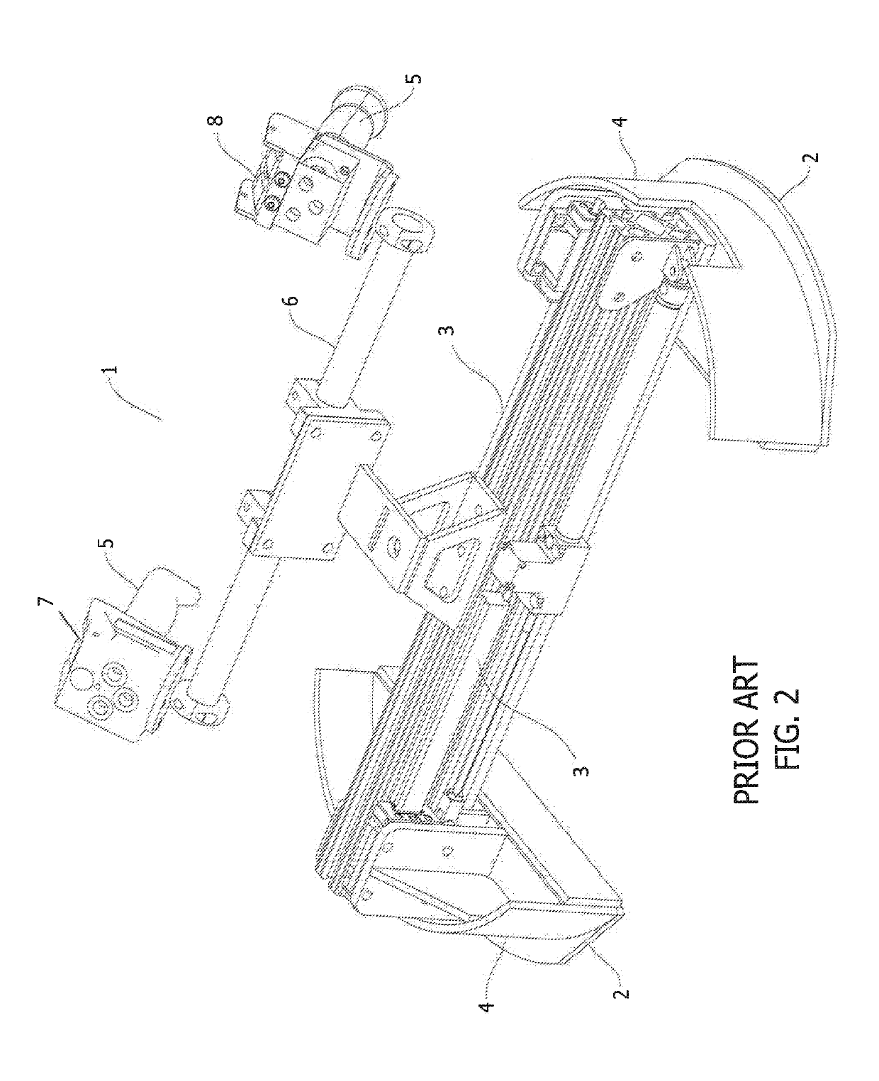
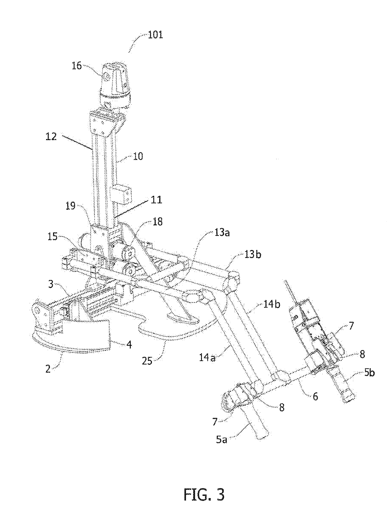
[0021]The present disclosure provides an apparatus and system to reduce or eliminate the safety and ergonomic drawbacks of using the prior art tire manipulator to reposition a tire and provides for the efficient and safe manipulation of tires. Unless otherwise defined, all terms (including mechanical, technical, and scientific terms) used herein have the same meaning as commonly understood by one of ordinary skill in the art to which this present disclosure belongs. It will be further understood that terms used herein should be interpreted as having a meaning that is consistent with their meaning in the context of this specification and the relevant art and will not be interpreted in an idealized or overly formal sense unless expressly so defined herein. It will be understood that, terms such as first, second, etc. may be used herein to describe various elements or configurations, these elements or configurations should not be limited by these terms. These terms are only used to dis...


PUM


Abstract

A suspended tire manipulator for use by an operator in lifting a tire having a mounting aperture includes a first handle attached to a first proximal arm. The first proximal arm is connected to a first distal arm at an obtuse angle. The manipulator includes a rotary balancer pivotally mounted to the first distal arm. The rotary balancer provides a pivoting torque to the first distal arm in response to operator movements raising and lowering the manipulator via manual force applied at the handle. A vertical support has a lower end and an upper end. The lower end connects to the rotary balancer. The manipulator includes a pair of gripper shoes. The pair of gripper shoes are slidably mounted on a rail and move in opposite inboard and outboard directions on the rail.

Description

CROSS REFERENCE TO RELATED APPLICATION[0001]This application claims the benefit of and incorporates by reference the entirety of U.S. Provisional Patent Application No. 62 / 610,421 filed on Dec. 26, 2017.STATEMENT REGARDING FEDERALLY SPONSORED RESEARCH OR DEVELOPMENT[0002]Not applicable.SEQUENCE LISTING, TABLE OR COMPUTER PROGRAM ON COMPACT DISC[0003]Not applicable.FIELD OF INVENTION[0004]This invention relates generally to material handling devices and systems and more specifically to a device for lifting and relocating a tire.BACKGROUND OF THE INVENTION[0005]It is commonplace in both industrial and commercial applications that employees are called upon to move bulky and heavy objects from one location to another. Such tasks present a risk of injury not just to the employees directly involved in the relocation task, but to other employees in the vicinity of the involved employees. In addition, moving bulky objects in the workplace requires dedication of man-power and time resources,...

Claims


Application Information

Patent Timeline
IPC IPC(8): B65G47/91B66C1/54B66F9/18
CPCB65G47/917B65G47/914B66C1/54B66F9/185B65G57/24B65G2201/0273B66D3/18
Inventor SHANNAHAN, MIKE
Owner CYNERGY ERGONOMICS INC
Why Eureka
Try Eureka