
Sensor having separate antenna

a technology of sensor and antenna, applied in the field of sensors, can solve the problems of short circuit, damage to the circuit board, and deterioration of achieve the effect of increasing the quality of the wireless communication of the antenna

Active Publication Date: 2019-07-18
IR TEC INT
View PDF0 Cites 0 Cited by
  • Summary
  • Abstract
  • Description
  • Claims
  • Application Information

AI Technical Summary

Benefits of technology

Enhances wireless communication quality by preventing signal blockage and protecting the circuit board from external damage, ensuring clear transmission and reception of wireless signals.

Problems solved by technology

When the circuit board is sprinkled by water, short circuit may occur and damage the circuit board.
However, since the antenna 30 is embedded into the ceiling or the wall, the ceiling or the wall may block wireless signals of wireless communication of the antenna 30.
Then, the antenna 30 may not clearly transmit or receive the wireless signals, and quality of the wireless communication of the antenna may be deteriorated.

Method used


Image

  • Sensor having separate antenna
  • Sensor having separate antenna
  • Sensor having separate antenna

Examples


Embodiment Construction

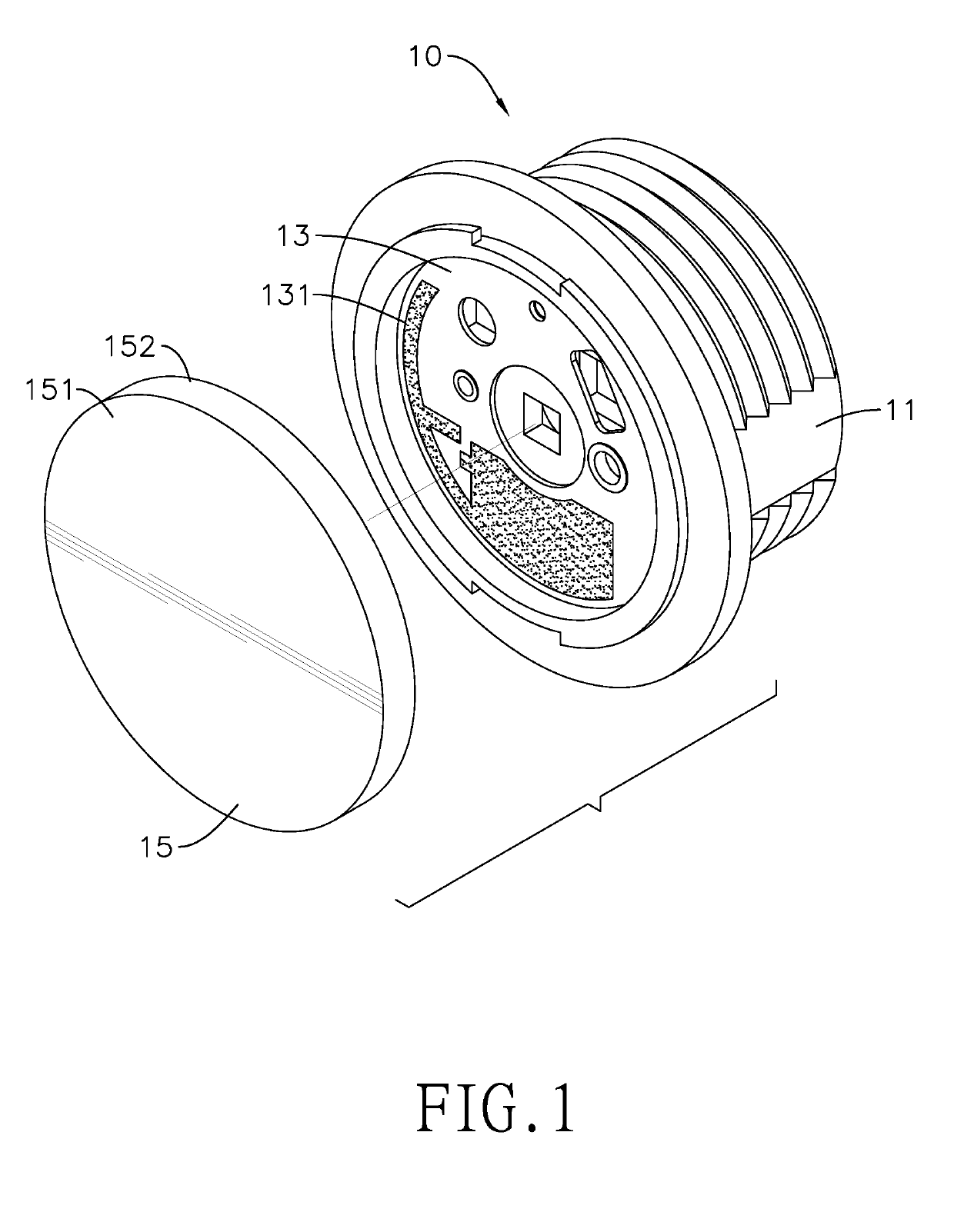
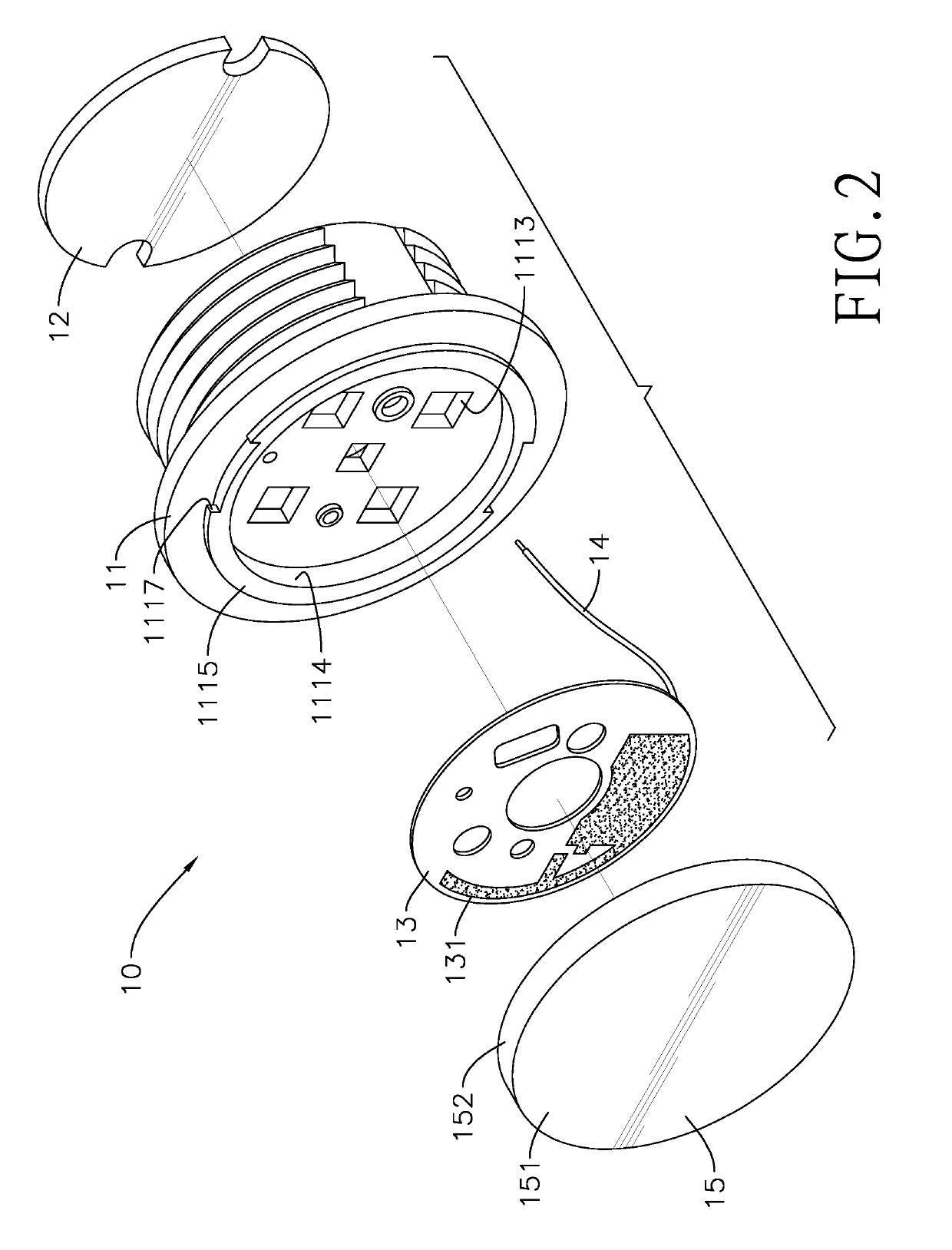
[0023]With reference to FIGS. 1 and 2, an embodiment of the present invention is a sensor 10 having a separate antenna. The sensor 10 comprises a shell 11, a circuit board 12, a nameplate 13, an antenna 131, and a connecting unit 14.

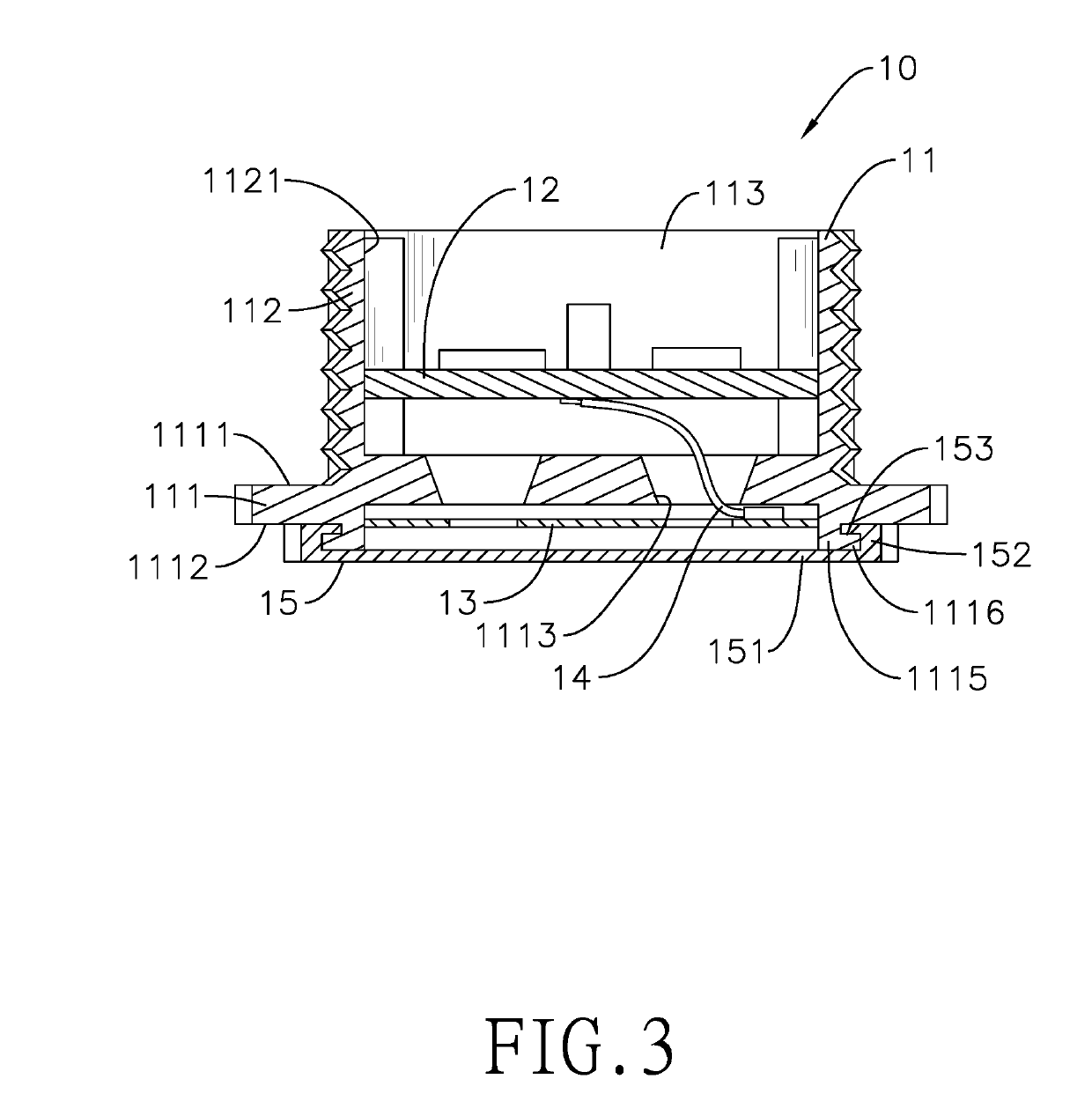
[0024]With reference to FIG. 3, the shell 11 comprises a substrate 111 and a tubular wall 112. The substrate 111 comprises a first surface 1111 and a second surface 1112. The first surface 1111 is opposite the second surface 1112. The tubular wall 112 is mounted on the first surface 1111 of the substrate 111, and a containing space 113 is formed within an inner surface 1121 of the tubular wall 112 and the first surface 1111 of the substrate 111.

[0025]The circuit board 12 is mounted in the containing space 113 of the shell 11. As shown in FIGS. 1 and 2, the nameplate 13 is mounted on the second surface 1112 of the substrate 111 of the shell 11. The antenna 131 is mounted on the nameplate 13 and is separate from the circuit board 12.

[0026]The connecting un...


PUM


Abstract

A sensor having a separate antenna includes a shell, a circuit board, a nameplate, an antenna, and a connecting unit. The shell includes a substrate and a tubular wall. The tubular wall is mounted on a first surface of the substrate to form a containing space. The circuit board is mounted in the containing space. The nameplate is mounted on a second surface of the substrate which is opposite the first surface. The antenna is mounted on the nameplate and is separate from the circuit board. The connecting unit is electrically connected between the antenna and the circuit board, and is mounted through the substrate. The antenna may be mounted outside of the containing space. When the sensor is mounted on a ceiling, the ceiling may not block wireless signals, and quality of wireless communication of the antenna may be improved.

Description

BACKGROUND OF THE INVENTION1. Field of the Invention[0001]The present invention relates to a sensor, and particularly to a sensor having a separate antenna.2. Description of the Related Art[0002]A conventional sensor senses changes of the environmental condition, and provides a control signal according to the changes of the environmental condition. The conventional sensor may transmit the control signal to a device to control the device. For example, a sensor of a lamp may sense changes of luminance of the environmental light or a motion of an object.[0003]When the luminance of the environmental light is changed or someone or something is moving within a detection range of the sensor, the sensor of the lamp may sense the changes of the environmental light, and the sensor of the lamp may transmit the control signal to the lamp to control the lamp. For example, when the sensor senses that the luminance of the environment becomes darker, the sensor controls the lamp to be brightened. W...

Claims


Application Information

Patent Timeline
Patent Type & Authority Applications(United States)
IPC IPC(8): H01Q1/42H05K7/14H01Q1/36H05K5/03G01D11/24
CPCH01Q1/42H05K7/1427G01J1/4204H05K5/03G01D11/245H01Q1/36H01Q1/38H01Q1/44G01J1/0219G01J3/0264
Inventor HUANG, WEN-ILIN, SHIH-TSUNGWANG, WEN-HSIANG
Owner IR TEC INT
Learn More