
Device and Method for Manufacturing Cylindrical Member

Active Publication Date: 2019-08-01
YOKOHAMA RUBBER CO LTD
View PDF2 Cites 0 Cited by
  • Summary
  • Abstract
  • Description
  • Claims
  • Application Information

AI Technical Summary

Benefits of technology

[0021]According to the present technology, using a mechanism, including the rotation shaft coaxial with the drum shaft and disposed separated from the drum shaft in a drum width direction, a base portion, and an arm, the first end portion of the band-like rubber member is pressed and held on the outer circumferential surface of the forming drum. Accordingly, even for forming drums having different specifications, the first end portion of the band-like rubber member can be securely fixed on the outer circumferential surface of the forming drum at a predetermined position by the arm. Moreover, by rotating the arm in a direction in which the front end portion of the arm moves away from the outer circumferential surface of the forming drum, the band

Problems solved by technology

However, the adhesion pad may be unable to be installed depending on the specifications of the forming drum.
This tracking device cannot be used in forming drums that include an expanding molding bladder on the drum outer ci

Method used


Image

  • Device and Method for Manufacturing Cylindrical Member
  • Device and Method for Manufacturing Cylindrical Member
  • Device and Method for Manufacturing Cylindrical Member

Examples


Example

[0031]Hereinafter, a device and method for manufacturing a cylindrical member of the present technology will be specifically described based on embodiments illustrated in the drawings.

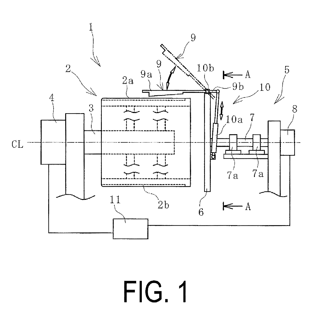
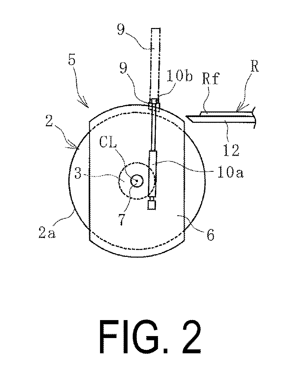
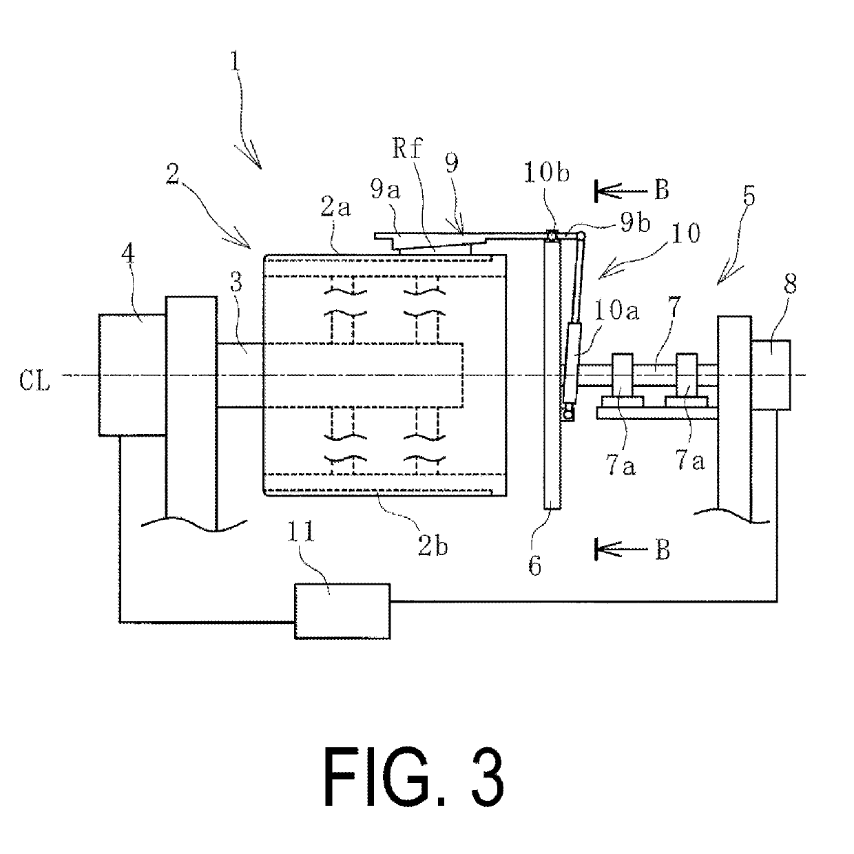
[0032]A device 1 for manufacturing a cylindrical member (hereinafter, referred to as manufacturing device 1) according to an embodiment of the present technology illustrated in FIG. 1 and FIG. 2 is provided with a forming drum 2 and a holder 5. The manufacturing device 1 forms an unvulcanized band-like rubber member R into a cylindrical member C as illustrated in FIG. 6. Examples of the cylindrical member C include a tire tread rubber, a side rubber, and various members used in the manufacture of a tire and other rubber products.

[0033]The forming drum 2 is a cylindrical body including a drum shaft 3 and is cantilevered by a frame or the like. At least a portion of the forming drum 2 can be expanded and contracted in the radial direction. One end portion of the drum shaft 3 is connected to a drum shaft ...


PUM

PropertyMeasurementUnit
Shapeaaaaaaaaaa
Angular velocityaaaaaaaaaa

Abstract

A cylindrical member manufacturing device is provided.
A rear end of an arm is rotatably supported by a base fixed to a rotation shaft coaxial with a drum shaft and separated from the drum shaft in a drum width direction; the arm is set to rotate in a direction so that a front end moves toward and away from an outer circumferential surface of a forming drum; and the base , the arm, and the rotation shaft are integrally rotated about the rotation shaft with the rotating forming drum with the front end moved toward the outer circumferential surface and the arm pressing a front end of a band-like rubber member disposed on the outer circumferential surface and holding a first end on the outer circumferential surface in order to wind the band-like rubber member around the outer circumferential surface and form the band-like rubber member into a cylindrical shape.

Description

TECHNICAL FIELD[0001]The present technology relates to a device and method for manufacturing a cylindrical member and particularly relates to a device and method for manufacturing a cylindrical member with high versatility in which, when winding a band-like rubber member and forming the band-like rubber member into a cylindrical shape, a first end portion corresponding to a winding starting point of the band-like rubber member can be securely fixed to an outer circumferential surface of a forming drum of various types at a predetermined position.BACKGROUND ART[0002]In the tire manufacturing process, various cylindrical members such as a tread rubber, a side rubber, and the like are manufactured using an unvulcanized band-like rubber member. In manufacturing these cylindrical members, for example, a band-like rubber member is wound around the outer circumferential surface of a forming drum and formed into a cylindrical shape. At this time, a method may be used that includes adhering / ...

Claims


Application Information

Patent Timeline
IPC IPC(8): B29D30/26
CPCB29D30/26B29L2022/025B29D2030/2614B29C53/56B29C65/7841B29C65/7844B29D2030/2685
Inventor FURUBAYASHI, YUKI
Owner YOKOHAMA RUBBER CO LTD
Learn More