
Vehicle circuit body

Active Publication Date: 2021-04-01
YAZAKI CORP
View PDF0 Cites 0 Cited by
  • Summary
  • Abstract
  • Description
  • Claims
  • Application Information

AI Technical Summary

Benefits of technology

The patent text describes a vehicle circuit body that can better fit the shape of the vehicle's body panel, making it more versatile and efficient. The technical effect of this innovation is better performance and reliability of the vehicle's circuit body.

Problems solved by technology

However, it is difficult to bend a thick electric wire in accordance with the shape of the body panel, and it is difficult to arrange the thick electric wire along the concave and convex shapes of the body panel.
However, it is necessary to prepare vehicle wiring members having different shapes in accordance with the body panel, which is not practical.
Such a large-size vehicle wiring member is difficult to be wired to the body panel, and it is also difficult to package and transport.
Moreover, in the case where a part of the vehicle circuit body of Patent Literature 1 is formed of the braid, it is technically difficult to flow a large current therethrough, and thus current capacity thereof tends to be reduced.
Therefore, applications in which the vehicle circuit body can be used are limited.

Method used


Image

  • Vehicle circuit body
  • Vehicle circuit body
  • Vehicle circuit body

Examples


first embodiment

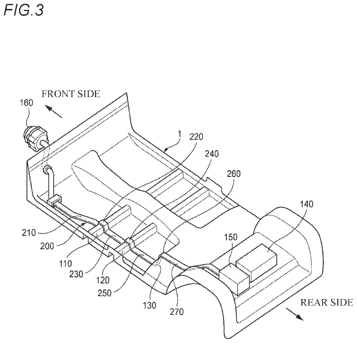
[0068]FIG. 3 is a perspective view showing an example of wiring a vehicle circuit body of a first embodiment according to the present invention to a body panel. When used as a battery cable, a vehicle circuit body 200 is wired along the body panel 1 across a front cross member 110 on a front (Fr) side of a vehicle, a rear cross member 120 on a rear (Rr) side, and a rear floor 130 on the rear (Rr) side of the rear cross member 120. As a result, the vehicle circuit body 200 can connect an alternator 160 and the like on the front side to a fuse box 150 which is connected to a battery 140 on the rear side.

[0069]In the first embodiment, the battery cable that connects the fuse box 150 and the alternator 160 is constituted by the single vehicle circuit body 200, and it is needless to say that the battery cable can also be constituted by a vehicle circuit body which is divided into a plurality of parts in a longitudinal direction. The divided vehicle circuit body is electrically connected ...

second embodiment

[0097]As described above, according to the vehicle circuit body of the second embodiment according to the present invention, the wiring material can be bent to any one side of the front and back sides. Therefore, for example, in cases where bending directions are different, such as the case where the wire harness is wired in the vehicle and the case where the wire harness is packed, the wiring material can be bent to a desired side.

[0098]Subsequently, a vehicle circuit body of a third embodiment according to the present invention will be described. The vehicle circuit body of the third embodiment differs from the vehicle circuit body of the first embodiment or the second embodiment in a position where the bent portion is provided. Therefore, the position where the bent portion is provided will be described in detail herein, and changed descriptions of configurations common to those of the first embodiment or the second embodiment will be omitted. FIG. 8 is a side view of the vehicle...

third embodiment

[0102]The vehicle circuit body of the third embodiment according to the present invention can obtain the following effects by intentionally providing the bent portions 801, 802 at the flat locations. That is, by adopting the structure in which the bent portions can be arranged not only at the inner corner or the outer corner having concave or convex shapes on the body panel 1 but also at the flat locations, the bent portions can be provided substantially anywhere in the vehicle circuit body. Since bent locations can be freely provided in the vehicle circuit body in this way, a degree of freedom in designing bent locations of the wire harness for packing is significantly improved.

[0103]According to the vehicle circuit body of the third embodiment according to the present invention, the bent portions 801, 802 wired at the flat locations can be expanded and contracted in a longitudinal direction. Therefore, dimensional tolerances of the rigid portions 301, 303, 305, 307, 309, 401, 403,...


PUM


Abstract

A vehicle circuit body is provided. The vehicle circuit body includes a bent portion which is formed by bending a plurality of conductor plates with a convex shape toward one side of a lamination direction in which the plurality of conductor plates are laminated, the plurality of conductor plates being laminated such that adjacent conductor plates are spaced apart from each other; and a rigid portion where the plurality of conductor plates extending from the bent portion are joined together to form a single layer. The bent portion is arranged at a position which faces an inner corner or outer corner of a concave-convex shape formed on a body panel.

Description

CROSS-REFERENCE TO RELATED APPLICATIONS[0001]This application is based on and claims priority under 35 USC 119 from Japanese Patent Application No. 2019-177673 filed on Sep. 27, 2019, the contents of which are incorporated herein by reference.TECHNICAL FIELD[0002]The present invention relates to a vehicle circuit body.BACKGROUND ART[0003]Patent Literature 1 discloses a vehicle circuit body that can be wired along concave and convex shapes of a body panel and that can realize a reduction in size.[0004]Patent Literature 1: JP-A-2019-043161[0005]In a case where a vehicle wiring member, such as a battery cable, is wired in a vehicle interior, it is required to perform the wiring along concave and convex shapes of a body panel due to needs for expanding living space in the vehicle interior. In order to arrange the vehicle wiring member along the body panel, it is necessary to bend the vehicle wiring member in accordance with a shape of the body panel.[0006]However, it is difficult to ben...

Claims


Application Information

Patent Timeline
IPC IPC(8): B60R16/02H01B7/04H01B7/08
CPCB60R16/0215H01B7/08H01B7/041H01B7/0823H01B7/009B60R16/0207
Inventor YAMAGUCHI, HAYATOTSUBAKI, AKIRAOKUDA, SADAHARUTAKAMATSU, MASAHIRO
Owner YAZAKI CORP
Learn More