
Image forming apparatus and control method therefor

Active Publication Date: 2019-10-03
CANON KK
View PDF1 Cites 3 Cited by
  • Summary
  • Abstract
  • Description
  • Claims
  • Application Information

AI Technical Summary

Benefits of technology

The invention allows for the printhead of an image forming apparatus to have the right temperature adjustment without using too much power.

Problems solved by technology

However, in Japanese Patent Laid-Open No. 2007-223144, the target temperature of the entire head is set high based on a temperature detected by each head unit, so the power consumption is large.
Further, in Japanese Patent Laid-Open No. 2007-223144, the highest temperature is set as the target temperature adjustment temperature of the entire head unit and the entire head undesirably stays in a high temperature state.

Method used


Image

  • Image forming apparatus and control method therefor
  • Image forming apparatus and control method therefor
  • Image forming apparatus and control method therefor

Examples


first embodiment

[0043]An embodiment of the present invention will be described below. In this embodiment, the printhead will be explained using a full-line printhead.

[0044][Overview of Arrangement of Printhead]

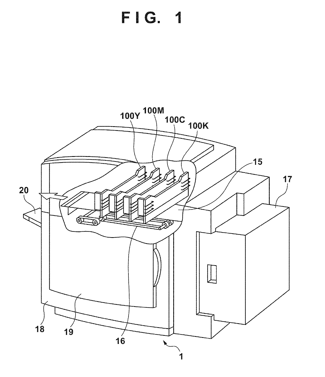
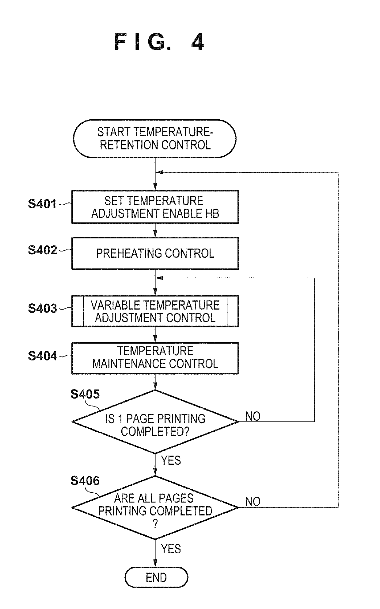
[0045]FIG. 3 is a view for explaining an overview of the arrangement of a printhead 100 according to this embodiment. As described above, a plurality of element substrates 301 are arrayed along the printing width in one printhead 100 according to this embodiment. That is, the plurality of element substrates 301 shown in FIG. 3 are arrayed in a direction (main scanning direction) perpendicular to the direction (sheet conveyance direction) of an arrow shown in FIG. 1. A plurality of sub-heaters (heat-up units) 302 are provided on one element substrate 301. Although the arrangement of the sub-heaters 302 is not particularly limited, they are arranged so that the provided sub-heaters 302 can adjust the temperature of the entire region of the corresponding element substrate 301. In this embodiment...

example

[0066]The feature of the present invention will be described in more detail in comparison with the conventional arrangement.

[0067](Case of Conventional Arrangement)

[0068]An example of an operation in the conventional arrangement will be described with reference to FIGS. 7 to 9C. An example of controlling the target temperature of the element substrate as the constant target temperature T1 regardless of the temperature distribution within the element substrate will be explained as a related art to be compared with the present invention. In other words, the temperature is maintained so that the lowest temperature within the element substrate becomes the target temperature T1 regardless of the temperature distribution within the element substrate.

[0069]FIG. 7 shows an example of the temperature distribution of a conventional printhead when a partially high-duty image is printed. An example of performing a print operation using five element substrates HB5 to HB9 out of a plurality of el...


PUM


Abstract

An image forming apparatus comprises: a printhead in which a plurality of element substrates for discharging a print material are arranged; a heating unit that maintains a temperature within the element substrate at a target temperature for each of the plurality of element substrates; a detection unit that detects the temperature within the element substrate for each of the plurality of element substrates; and a control unit that, for each of the plurality of element substrates, compares a highest temperature within the element substrate that is detected by the detection unit with a predetermined threshold, and if the highest temperature exceeds the predetermined threshold, sets the target temperature for the element substrate a temperature which is higher than a target temperature set when the highest temperature does not exceed the predetermined threshold and lower than the predetermined threshold.

Description

BACKGROUND OF THE INVENTIONField of the Invention[0001]The present invention relates to an image forming apparatus and a control method therefor.Description of the Related Art[0002]An image forming apparatus with a printhead has conventionally used heat to discharge ink when performing a print operation. Temperature control to the heat is performed in the printhead.[0003]For example, Japanese Patent Laid-Open No. 2007-223144 discloses an arrangement of independently controlling an ink heater to achieve a set temperature in a heat unit configured to discharge ink.[0004]However, in Japanese Patent Laid-Open No. 2007-223144, the target temperature of the entire head is set high based on a temperature detected by each head unit, so the power consumption is large. Further, in Japanese Patent Laid-Open No. 2007-223144, the highest temperature is set as the target temperature adjustment temperature of the entire head unit and the entire head undesirably stays in a high temperature state.SU...

Claims


Application Information

Patent Timeline
IPC IPC(8): B41J2/045B41J29/38
CPCB41J2/04563B41J2/0452B41J29/38B41J2/0458B41J2/04528B41J2/04553
Inventor KANO, YUTAKAOIKAWA, YUHEICHIKUMA, TOSHIYUKI
Owner CANON KK
Learn More