Wireless communication method, control device, terminal and wireless communication system

Active Publication Date: 2021-09-02
NIPPON TELEGRAPH & TELEPHONE CORP
View PDF0 Cites 0 Cited by
  • Summary
  • Abstract
  • Description
  • Claims
  • Application Information

AI Technical Summary

Benefits of technology

[0025]According to the present disclosure, it is possible to suppress power consumption

Problems solved by technology

In a case where a facility utilization factor of the base station apparatus is reduced, insta

Method used


Image

  • Wireless communication method, control device, terminal and wireless communication system
  • Wireless communication method, control device, terminal and wireless communication system
  • Wireless communication method, control device, terminal and wireless communication system

Examples


Example

[0038]Hereinafter, an embodiment of the present disclosure will be described with reference to the drawings.

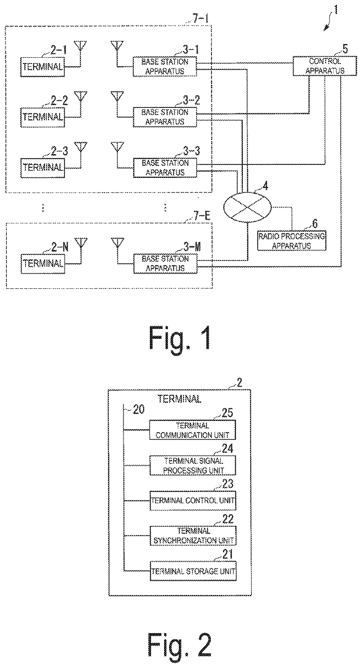
[0039]FIG. 1 is a diagram illustrating an example of a configuration of a radio communication system 1. The radio communication system 1 is a system executing communication in compliance with a plurality of radio schemes. The radio communication system 1 includes terminals 2-1 to 2-N (where N is an integer of 1 or greater), base station apparatuses 3-1 to 3-M (where M is an integer of 1 or greater), a communication line 4, a control apparatus 5, and a radio processing apparatus 6.

[0040]The radio communication system 1 includes regions 7-1 to 7-E (where E is an integer of 1 or greater) that are predetermined regions. In FIG. 1, in an example, the base station apparatuses 3-1 to 3-3 are located in the region 7-1. In an example, the terminals 2-1 to 2-3 are located in the region 7-1. In an example, the base station apparatus 3-M is located in the region 7-E. In an example, the te...


PUM


Abstract

A radio communication method executed by a control apparatus controlling a base station apparatus performing communication with a terminal in a predetermined region, and includes determining whether there is the terminal that is asynchronized in communication with the base station apparatus transmitting a synchronization signal, and controlling, in a case where it is determined that there is the asynchronized terminal, the base station apparatus to increase an allocation time of the synchronization signal in compliance with a radio scheme used by the asynchronized terminal or to shorten an allocation cycle of the synchronization signal.

Description

TECHNICAL FIELD[0001]The present disclosure relates to a radio communication method, a control apparatus, a terminal, and a radio communication system.BACKGROUND ART[0002]There is a radio communication system including a radio signal processing apparatus that is an apparatus executing radio signal processing, a base station apparatus such as an access point, a slave station, or a remote radio unit (RRU), and a terminal such as an Internet of Things (IoT) device having various requirements. Each terminal performs communication with a base station apparatus according to a radio scheme appropriate for requirements of the terminal. The radio scheme is, for example, LoRa, SigFox, or NB-IoT.[0003]A battery capacity of an IoT device may be smaller than a battery capacity of a terminal other than the IoT device. A communication of the IoT device may be less frequent than a communication of a terminal other than the IoT device. Thus, in a case where a terminal such as an IoT device performs ...

Claims


Application Information

Patent Timeline
IPC IPC(8): H04W56/00H04W72/12
CPCH04W56/0015H04W72/1263H04W52/02H04W56/00Y02D30/70
Inventor KATAYAMA, YOHEITANIGUCHI, ATSUSHISHIMIZU, KENJIYAMAZAKI, TAKAHIRONAYA, MAIKO
Owner NIPPON TELEGRAPH & TELEPHONE CORP
Why Eureka
Try Eureka