

Driving device
- Summary
- Abstract
- Description
- Claims
- Application Information
AI Technical Summary
Benefits of technology
Problems solved by technology
Method used
Image

Examples
first embodiment
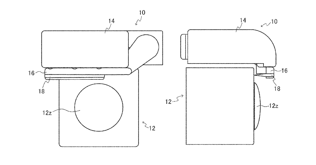
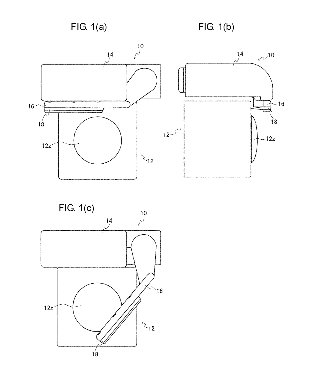
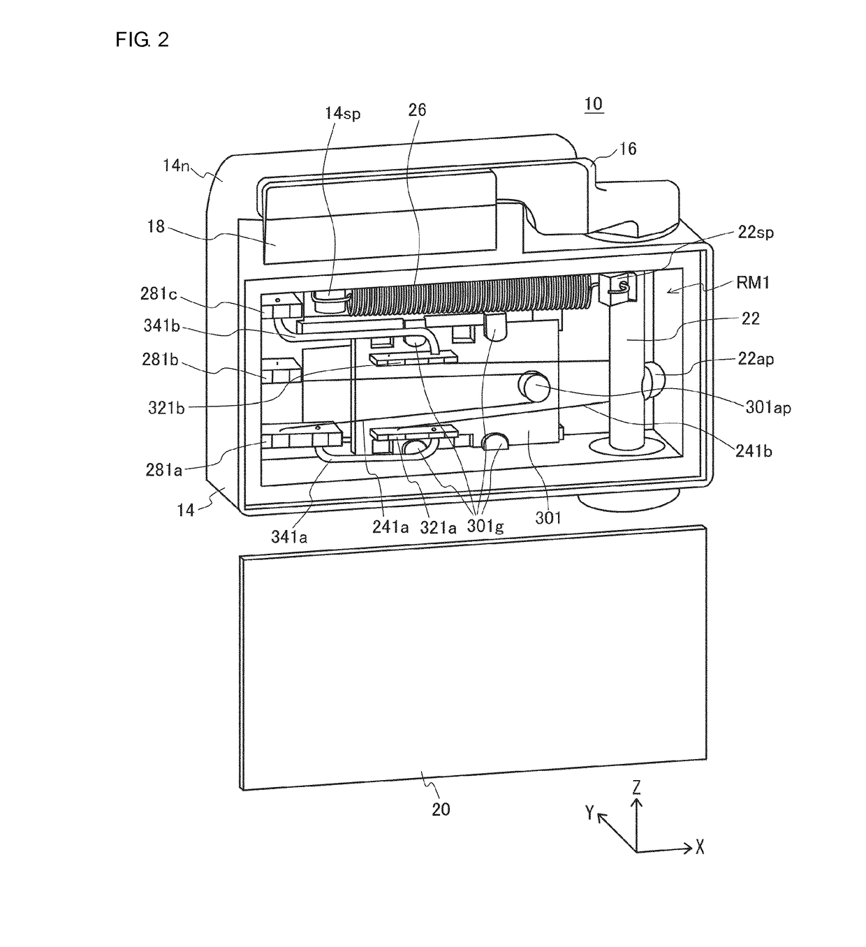
[0028]As shown in FIGS. 1(A) through 1(C) and FIG. 2, a raindrop removing device 10 of a first embodiment is a device that is provided in a rear section of an automobile along with a camera 12 so as to remove raindrops attached to a lens 12z, and includes a housing 14 in which a rectangular parallelepiped storage room RM1 is formed. In the case where an X-axis is assigned to a width direction of the housing 14, a Y-axis is assigned to a thickness direction of the housing 14, and a Z-axis (reference axis) is assigned to a height direction of the housing 14, the storage room RM1 is open to a negative side of the Y-axis direction. Two inner side surfaces opposing each other and constituting the storage room RM1 are orthogonal to the X-axis or Z-axis, and a bottom surface also constituting the storage room RM1 is orthogonal to the Y-axis. Further, two outer side surfaces facing opposite sides to each other and constituting the housing 14 are orthogonal to the X-axis or Z-axis.
[0029]A co...
second embodiment
[0057]As shown in FIG. 4, a raindrop removing device 10 of a second embodiment, when compared to the raindrop removing device 10 shown in FIG. 2, employs an SMA holding member 222h in place of the SMA post 22ap, shape memory alloys 242a and 242b in place of the shape memory alloys 241a and 241b, power supply terminals 282a through 282c in place of the power supply terminals 281a through 281c, a relay member 302 in place of the relay member 301, guides 302g in place of the guides 301g, relay terminals (specific power supply terminals) 322a through 322c in place of the relay terminals 321a and 321b, and a lead wire 342 in place of the lead wires 341a and 341b. Further, the materials of the relay member 302, the SMA holding member 222h, the rotational shaft 22, and the spring post 22sp are a metal such as aluminum or the like (a conductor in which plating or the like is performed on a surface of a resin such as PPS or the like may also be used). The bias spring 26 is formed of a spring...
third embodiment
[0075]As shown in FIG. 5, a raindrop removing device 10 of a third embodiment, when compared to the raindrop removing device 10 shown in FIG. 2, employs an SMA holding member 223h in place of the SMA post 22ap, shape memory alloys 243a and 243b in place of the shape memory alloys 241a and 241b, power supply terminals 283a through 283c in place of the power supply terminals 281a through 281c, a relay member 303 in place of the relay member 301, a pin 303p in place of the guides 301g, relay terminals (specific power supply terminals) 323a through 323c in place of the relay terminals 321a and 321b, and a lead wire 343 in place of the lead wires 341a and 341b. Further, the materials of the relay member 303, the SMA holding member 223h, the rotational shaft 22, and the spring post 22sp are a metal such as aluminum or the like (a conductor in which plating or the like is performed on a surface of a resin such as PPS or the like may also be used). The bias spring 26 is formed of a spring m...
PUM
 Abstract
Description
Claims
Application Information