Fuel cell battery

Active Publication Date: 2019-10-03
HONDA MOTOR CO LTD
View PDF1 Cites 0 Cited by
  • Summary
  • Abstract
  • Description
  • Claims
  • Application Information

AI Technical Summary

Benefits of technology

[0005]However, as the number of the cells is increased, production errors of the components and piece-to-piece variations are cumulatively increased accordingly, so that the load cannot be uniformly applied to the cells in the stacking direction. Consequently, the contact pressure between the cells in the stack may be lowered, resulting in an increased electric resistance. As a result,

Problems solved by technology

However, as the number of the cells is increased, production errors of the components and piece-to-piece variations are cumulatively increased accordingly, so that the load cannot be uniformly applied to the ce

Method used


Image

  • Fuel cell battery
  • Fuel cell battery
  • Fuel cell battery

Examples


Embodiment Construction

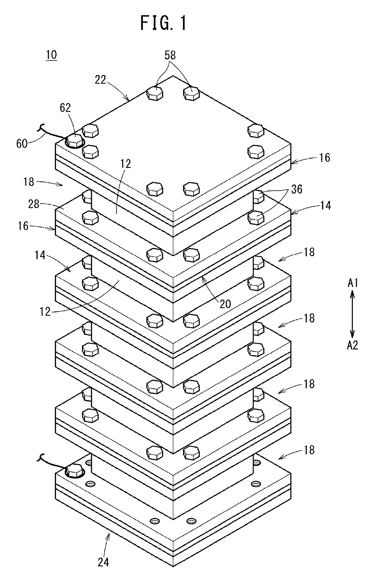
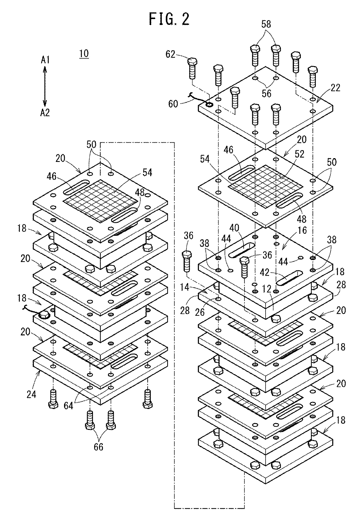
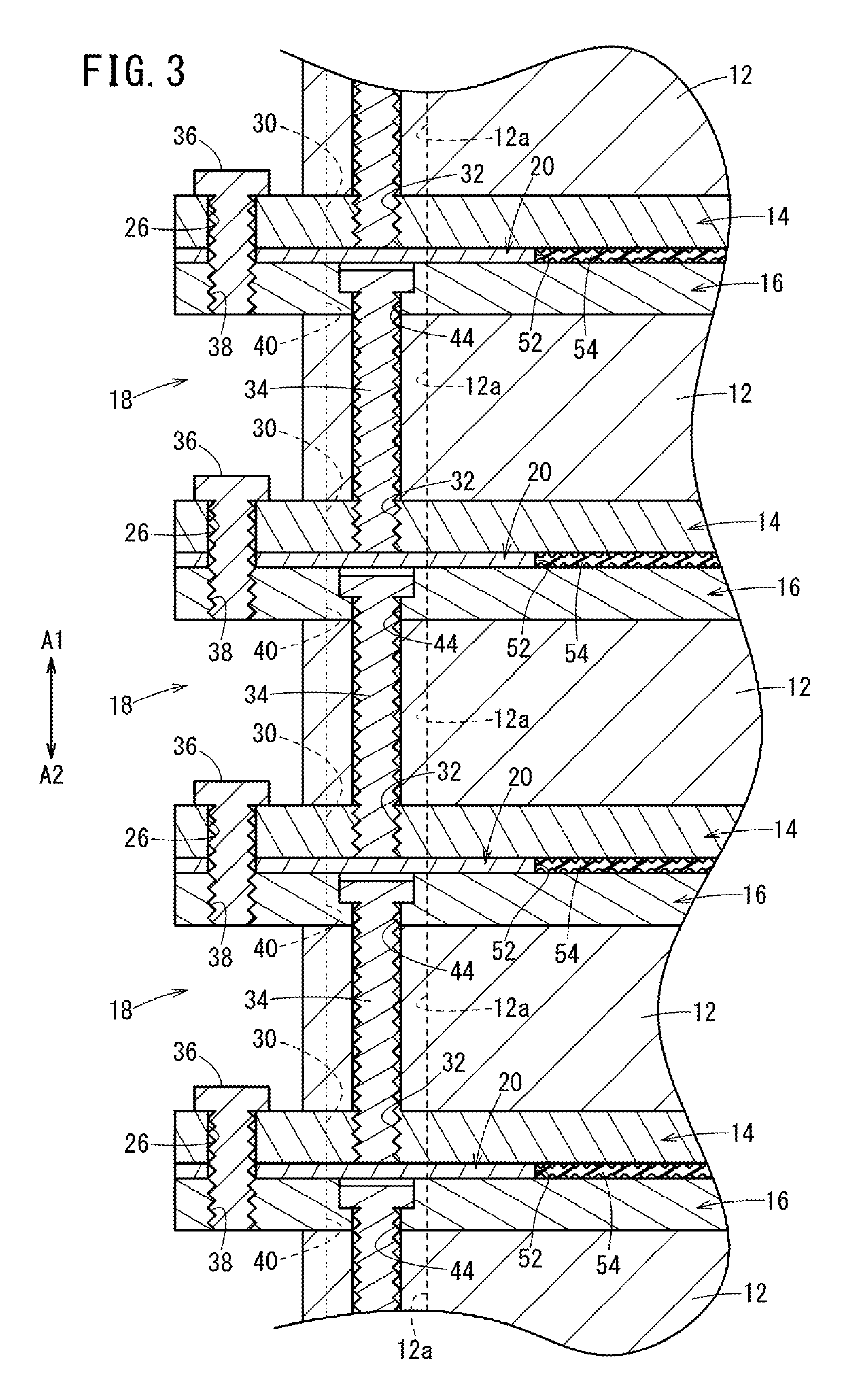
[0016]As shown in FIGS. 1 and 2, a fuel cell battery 10 according to an embodiment of the present invention contains stacks 18. The stack 18 is a module containing a cell 12, a base plate (first base) 14, and a cover plate (second base) 16. The base plate 14 is in contact with one end side of the cell 12, and the cover plate 16 is in contact with the other end side of the cell 12. The stack 18 may contain one or a plurality of the cells 12. In the fuel cell battery 10, a plurality of the stacks 18 are stacked together in a stacking direction, and a gasket 20 is interposed between the base plate 14 of the stack 18 and the cover plate 16 of the adjacent stack 18. In this embodiment, the fuel cell battery 10 contains five stacks 18 stacked together.

[0017]In the fuel cell battery 10 containing the stacks 18 stacked together, a top cover 22 is disposed at one end in the stacking direction indicated by arrows A1, A2 (i.e., an end in the direction of arrow A1), and a bottom cover 24 is dis...


PUM


Abstract

A fuel cell battery includes a plurality of stacks. Each of the stacks is a module containing a cell, and a base plate and a cover plate sandwiching the cell therebetween. In a state where the stacks are stacked together with a gasket being sandwiched between two adjacent stacks of the stacks, the two adjacent stacks are connected to each other by a connecting bolt. The gasket has, at a central part thereof, a contact plate that is elastic and electrically conductive. When the gasket is sandwiched between the two adjacent stacks, the contact plate is brought into abutment with the cover plate and the base plate.

Description

CROSS-REFERENCE TO RELATED APPLICATION[0001]This application is based upon and claims the benefit of priority from Japanese Patent Application No. 2018-064035 filed on Mar. 29, 2018, the contents of which are incorporated herein by reference.BACKGROUND OF THE INVENTIONField of the Invention[0002]The present invention relates to a fuel cell battery containing a plurality of cells stacked together.Description of the Related Art[0003]A fuel cell battery containing a plurality of cells stacked together has been known. For example, as disclosed in Japanese Patent No. 4136443, a stationary end plate is disposed at one end of a stack body of the stacked cells, and a movable plate is disposed at the other end. The movable plate is pressed toward the stack body by a cylinder of another stationary end plate provided at the other end, whereby a pressure is applied to the cells of the stack body. The stationary end plates disposed at the one end and the other end of the stack body are fixed in ...

Claims


Application Information

Patent Timeline
IPC IPC(8): H01M8/249H01M8/2465
CPCH01M8/249H01M8/2465H01M8/248H01M8/247Y02E60/50Y02P70/50H01M8/0276H01M8/241H01M8/2418H01M8/2457
Inventor TAKADA, HIDEAKI
Owner HONDA MOTOR CO LTD
Why Eureka
Try Eureka