Diaphragm with edge seal

a diaphragm and edge sealing technology, applied in the direction of machines/engines, flexible member pumps, positive displacement liquid engines, etc., to achieve the effect of high contact pressure and contact pressur

Active Publication Date: 2018-03-01
WANNER EGINEERING INC
View PDF13 Cites 0 Cited by
  • Summary
  • Abstract
  • Description
  • Claims
  • Application Information

AI Technical Summary

Benefits of technology

[0010]In operation, on each pressure stroke of the pump, pressure increases in both the hydraulic chamber and the pumping chamber. The increasing pressure forces the O-rings and outward to push on the lips extending from each face of the diaphragm. As force is applied to the sealing lips, the lips are forced against respective first and second groove walls. This sealing occurs even if there is some leakage past a respective O-ring. When the first and second lips are forced against the groove walls, high contact pressure is generated that resists leakage past the contacting surfaces to an atmospheric leak path. Moreover, as the pressure in the pumping and hydraulic chambers increases, the contact pressure of each of the sealing lips against the respective groove wall also increases. This creates a “self-energizing” seal to provide a sealing force. In addition, by the lips being forced tightly against the respective walls, any potential gap that the O-ring could extrude through is closed, having the same effect as an anti-extrusion backup ring.

Problems solved by technology

However, the second diaphragm facing the pumping chamber may need to be made of PTFE as it may come into contact with harsh fluids being pumped.

Method used


Image

  • Diaphragm with edge seal
  • Diaphragm with edge seal
  • Diaphragm with edge seal

Examples


first embodiment

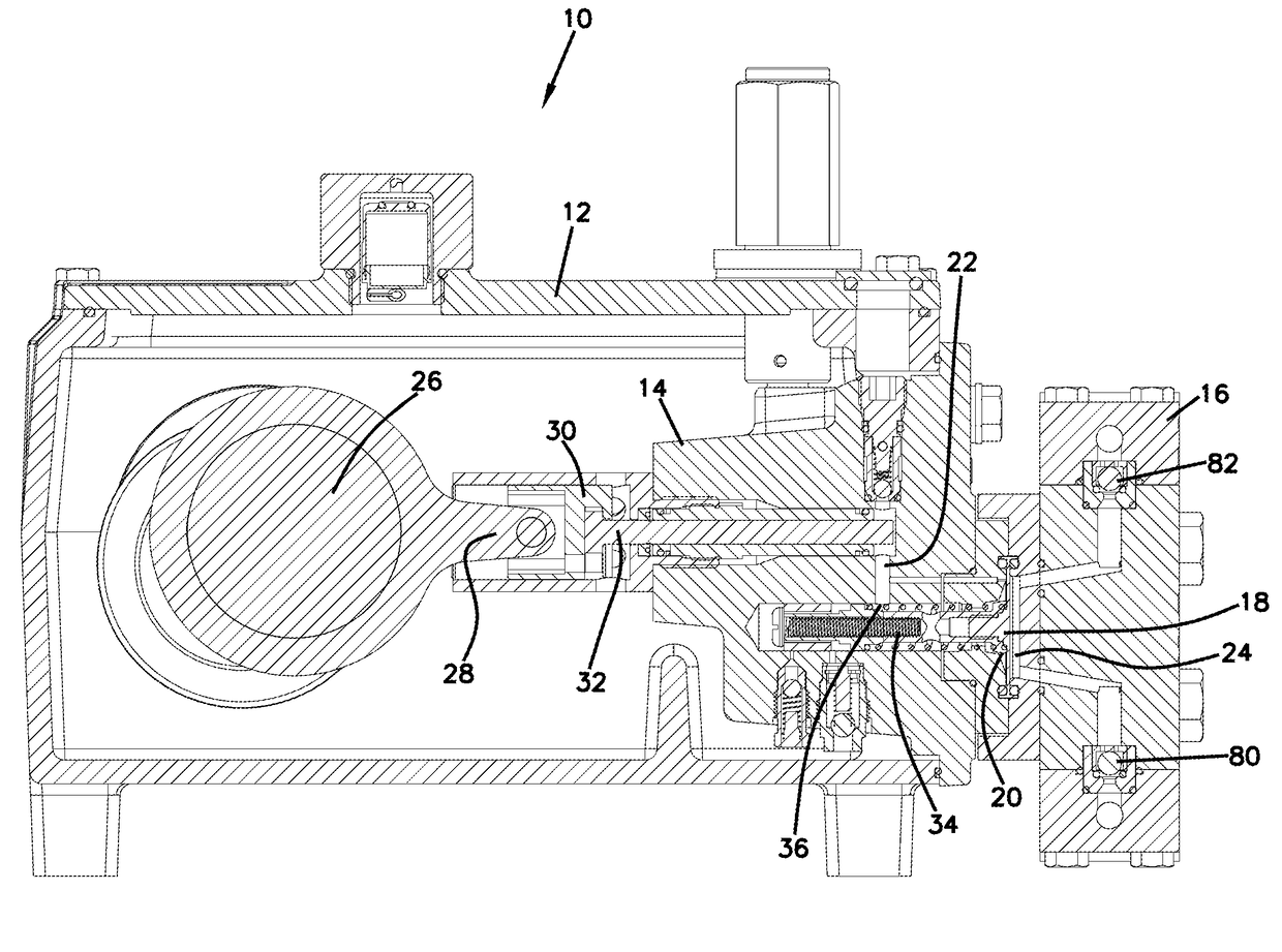
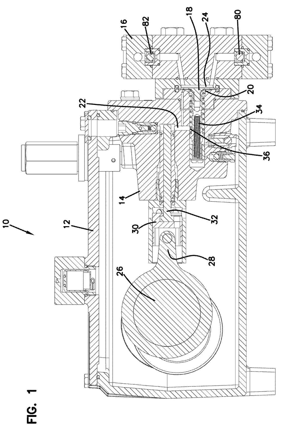
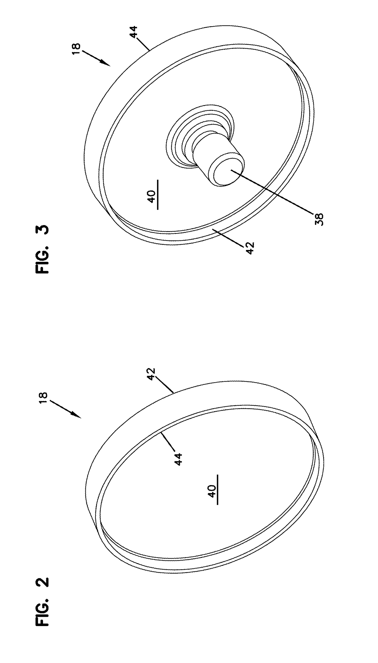
[0027]Referring to FIGS. 2-7, in a first embodiment, the diaphragm (18) is a monolithic element and includes a disk-shaped center planar portion (40) and a first lip (42) and a second lip (44) on the outermost edge of the disk shaped portion (40) and extending transversely to the planar disk portion (40). The first lip (42) is on the hydraulic chamber side of the diaphragm (18) and the second lip (44) is on the pumping chamber side of the diaphragm (18). A mounting portion (38) extends outward from the center of the face of the planar portion (40) on the hydraulic chamber side of the diaphragm (18). For metering pump applications pumping harsh fluids, the diaphragm (18) is typically made from a fluoropolymer and in particular may be made from polytetrafluoroethylene (PTFE), commonly marketed as TEFLON®, or may be made from GYLON®. The material used depends on whether the fluid being pumped is harsh and requires special materials that will not degrade if contacted by the fluid.

[0028]...

second embodiment

[0029]Referring now to FIG. 9, in a second embodiment, a double diaphragm arrangement (60) is used in diaphragm pumps for leak detection. In this embodiment, the pump (10) uses a first diaphragm (62) and a second diaphragm (64) attached to and separated by a porous mesh material (66). The first diaphragm (62) faces the hydraulic chamber (20) and has a single lip (70) that seals against the groove wall (50). The second diaphragm (64) is on the pumping chamber side and has a single lip (72) that seals against the groove wall (52). The double diaphragm arrangement also includes the first O-ring (46) and the second O-ring (48) as with diaphragm (10). The diaphragms (62), (64) may be made of the same or different materials. However, the diaphragm (64) may need to be made of PTFE as the diaphragm (64) may come into contact with harsh fluids being pumped.

[0030]In operation, on each pressure stroke of the pump (10), pressure increases in both the hydraulic chamber (20) and the pumping chamb...


PUM

PropertyMeasurementUnit
pressureaaaaaaaaaa
corrosiveaaaaaaaaaa
chemical resistanceaaaaaaaaaa

Abstract

A diaphragm (18) includes a disk-shaped center planar portion (40) and a first lip (42) and a second lip (44) on the outermost edge of the disk shaped portion (40) and extending transversely to the planar disk portion (40). The first lip (42) is on a first side of the diaphragm (18) and the second lip (44) is on an opposite side of the diaphragm (18). A mounting portion (38) extends outward from the center of the face of the planar portion (40) on the first side of the diaphragm (18). For metering pump applications pumping harsh fluids, the diaphragm (18) is typically made from a fluoropolymer and in particular may be made from polytetrafluoroethylene (PTFE).

Description

BACKGROUND OF THE INVENTIONField of the Invention[0001]The present direction is directed to a system and method for sealing diaphragms and to a diaphragm pump with an improved diaphragm sealing system.Prior Art[0002]Diaphragm pumps are pumps in which the pumped fluid is displaced by a diaphragm. In hydraulically driven pumps, the diaphragm is deflected by hydraulic fluid pressure forced against the diaphragm. Such pumps have proven to provide a superior combination of value, efficiency and reliability. However, maintaining a proper seal and extending the life of the diaphragm are challenges with diaphragm pumps.[0003]A further challenge with using diaphragms arises when harsh fluids that may be corrosive, caustic, or acidic must be pumped. Fluoropolymer materials including polytetrafluoroethylene (PTFE), commonly sold under the names TEFLON®, and GYLON® are often used for diaphragms in metering diaphragm pumps because of their chemical resistance. Such materials may resist harsh flu...

Claims


Application Information

Patent Timeline
Patent Type & Authority Applications(United States)
IPC IPC(8): F04B43/00F04B43/02F04B43/06
CPCF04B43/009G01M3/28F04B43/06F04B43/02F04B13/00F04B15/04F04B43/0054F04B43/067F04B43/0036F05B2280/4005F05C2225/04F05B2240/57F05B2210/11
Inventor POINDEXTER, DAVIDTAYLOR, NEIL
Owner WANNER EGINEERING INC
Why Eureka
Try Eureka