Flat cable electrical connector

a flat-wire electrical connector and cable technology, applied in the direction of coupling contact member, coupling device connection, coupling/disconnecting parts, etc., can solve the problem of not providing low-profile connectors, not meeting both requirements, and the angle of the corner portion is too small to provide satisfactory click sensation, etc. problem, to achieve the effect of large degree of pressure and large click sensation

Active Publication Date: 2008-03-25
HIROSE ELECTRIC GROUP
View PDF6 Cites 30 Cited by
  • Summary
  • Abstract
  • Description
  • Claims
  • Application Information

AI Technical Summary

Benefits of technology

[0009]Accordingly, it is an object of the present invention to provide a low-profile flat cable electrical connector capable of providing a satisfactory click sensation and maintaining a high contact pressure between the terminal and the flat cable.
[0011]The cam portion has such a shape that it is out of contact with the pressure receiving portion of the lever arm when the movable member is at the open position, thereby making it possible to insert the flat cable and in contact with the pressure receiving portion when the movable member is at the closed position. The pressure receiving portion has a shoulder and a concave indentation continued from the shoulder so that when the movable member moves to the closed position, the cam portion provides the pressure receiving portion with a highest pressure and when the movable member reaches the closed position, the cam portion rests in the concave indentation while maintaining a pressure that is lower than the highest pressure.
[0013]The cam portion may have an elongated circular or elliptic cross-section and the concave indentation may have such a curved shape as to fit to a shape of said cam portion. The curved portion of the elongated circular or ecliptic cam makes the contact position with the pressure receiving portion move smoothly and the concave curve of the concave indentation makes stable the final position of the cam at the closed position.

Problems solved by technology

However, the above connector fails to meet both the requirements at the same time.
However, if the angle is too large, no low-profile connector is provided.
In other words, when the satisfactory contact pressure is maintained, the angle of the corner portion is too small to provide a satisfactory click sensation.

Method used


Image

  • Flat cable electrical connector
  • Flat cable electrical connector
  • Flat cable electrical connector

Examples


Embodiment Construction

[0025]An embodiment of the invention will now be described with reference to FIGS. 1-4.

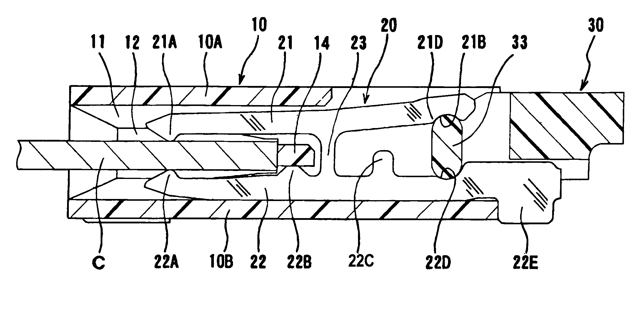
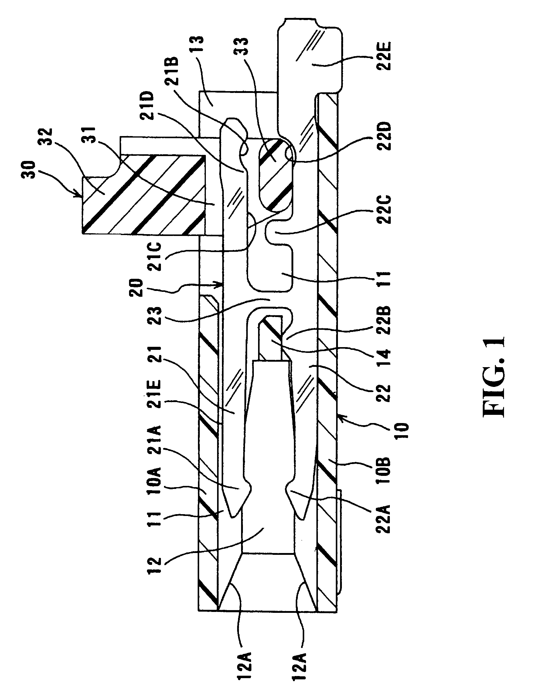
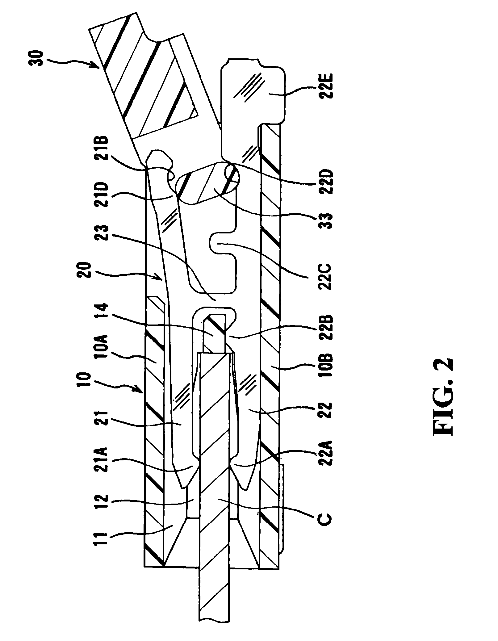
[0026]In FIG. 1, a plurality of terminals are arranged at predetermined intervals in the first direction perpendicular to the drawing sheet. A housing 10 is made of a dielectric material so as to provide a substantially rectangular form which has a plurality of slits 11 between an upper wall 10A and a bottom wall 10B of the housing 10 for receiving the terminals. The thickness of the slit 11 is substantially equal to the thickness of the terminal which is inserted into the housing from right to left. The slits 11 are arranged at predetermined intervals in the first direction and extend laterally through the housing 10.

[0027]A cable receiving cavity 12 is provided in the left half of the housing 10 so as to communicate with the slits 11. The height of the cable receiving cavity 12 is slightly greater than the thickness of a flat cable to be inserted. The cable receiving cavity 12 has tapered openin...


PUM


Abstract

When the movable member (30) is at the open position, the cam portion (33) of the movable member (30) is out of contact with the pressure receiving portion of a lever arm (21), making it possible to insert a flat cable into the connector on the contact side. When the movable member (30) is at the closed position, the cam portion (33) comes into contact with the pressure receiving portion that consists of a shoulder (21D) and a concave indentation (21B). While the movable member (30) is moving to the closed position, the cam portion (33) pushes the shoulder (21D) to provide the pressure receiving portion with the highest pressure. When the movable member (30) reaches the closed position, the cam portion (33) rests in the concave indentation (21B) while maintaining a pressure less than the highest pressure.

Description

BACKGROUND OF THE INVENTION[0001]1. Field of the Invention[0002]The present invention relates to electrical connectors for flat cables.[0003]2. Description of the Related Art[0004]Japanese Patent No. 3047862 discloses a connector of this type. As shown in FIGS. 5(A) and 5(B), this connector includes a plurality of terminals 51 arranged in the direction perpendicular to the drawing sheet. The terminal 51 has upper and lower arms 52 and 53 which are connected by a linking section 54, forming a substantially H-shape. The lower arm 53 is in contact with the bottom wall 56 of a housing 55, with one of its ends 57 engaged with the housing 55. The other end forms a connection section 58 outside the housing 55. The upper arm 52 is made flexible and has a contact portion 52A at one end to cooperate with the contact portion 53A of the lower arm 53 for holding a flat cable P between them for contact. See FIG. 5(B). At the other end, it has a corner portion 52B to receive a force from a movable...

Claims


Application Information

Patent Timeline
Patent Type & Authority Patents(United States)
IPC IPC(8): H01R12/24
CPCH01R13/193H01R12/79H01R12/88
Inventor TAKASHITA, YOSHINORI
Owner HIROSE ELECTRIC GROUP
Why Eureka
Try Eureka