Electric power tool with optimized operating range

a technology of operating range and electric power tools, which is applied in the direction of portable power-driven tools, manufacturing tools, instruments, etc., can solve the problems of less-skilled users, unsatisfactory results of work, and inability to keep contact pressure constant,

Inactive Publication Date: 2009-03-17
ROBERT BOSCH GMBH
View PDF34 Cites 32 Cited by
  • Summary
  • Abstract
  • Description
  • Claims
  • Application Information

AI Technical Summary

Benefits of technology

[0003]The electric power tool of the invention, having an electric motor used to drive a tool, is distinguished in that a sensor unit that detects the contact pressure of the tool against a workpiece cooperates with a signal transducer. Because the contact pressure employed is visible to the user by means of the signal transducer, the user can tell whether he is exerting a contact pressure within an optimized operating range. The optimized operating range assures excellent outcomes of the work. If the contact pressure is above the contact pressure of the optimized operating range, the user can lower the contact pressure because of the feedback from the signal transducer. Conversely, if an overly low value for the contact pressure being exerted is displayed, the user can increase the contact pressure. The feedback from the signal transducer can, in addition to the indication described above, also be made possible by displaying whether the value of the contact pressure is being kept constant during the work process, or whether the user is varying it unintentionally. With the electric power tool of the invention, it is thus possible to monitor the contact pressure and, by suitable provisions made by the user, to keep it at a suitable value, and in particular keep it constant, during a work process. Moreover, the electric power tool of the invention satisfies the prerequisite that a work process after being interrupted will be continued with the same contact pressure.
[0004]According to the invention, it is moreover provided in addition or as an alternative that the electric power tool has an electric motor, serving to drive a tool, a control and / or regulating unit, which serves to guide the operation of the electric motor and which cooperates with the sensor unit, which detects the contact pressure of the tool against the workpiece. In this way, the control and / or regulating unit is capable of adapting the guidance of the operation of the electric motor to the contact pressure being employed by the user at that moment. The quality of the outcome of the work attainable with an electric power tool is defined by a plurality of work parameters. These work parameters are among others the contact pressure and work parameters that are affected by the electric motor, such as the torque and the rpm of the tool. For performing an optimized work process, it is necessary that these work parameters be adapted to one another. The electric power tool of the invention satisfies the prerequisite for this, which is that by means of the control and / or regulating unit, the optimized work parameters of torque and / or rpm that pertain to the contact pressure being employed at the moment are set. The user of the electric power tool can thus devote his full concentration to the work process, for instance the grinding or drilling operation, yet still has the certainty that the work process is taking place within the optimized operating range, at least with regard to the detected or measured variables. If the user changes the contact pressure, the control and / or regulating unit responds by readjustment, for instance of the torque, so that the work process remains within the desirable range, and an optimal outcome of the work is attained.

Problems solved by technology

The probability is very high that the contact pressure will not be kept constant over the duration of a work process by the user, and hence the work process will not be carried out uniformly.
Less-skilled users will attain only less-satisfactory results of their work.

Method used


Image

  • Electric power tool with optimized operating range
  • Electric power tool with optimized operating range
  • Electric power tool with optimized operating range

Examples


Embodiment Construction

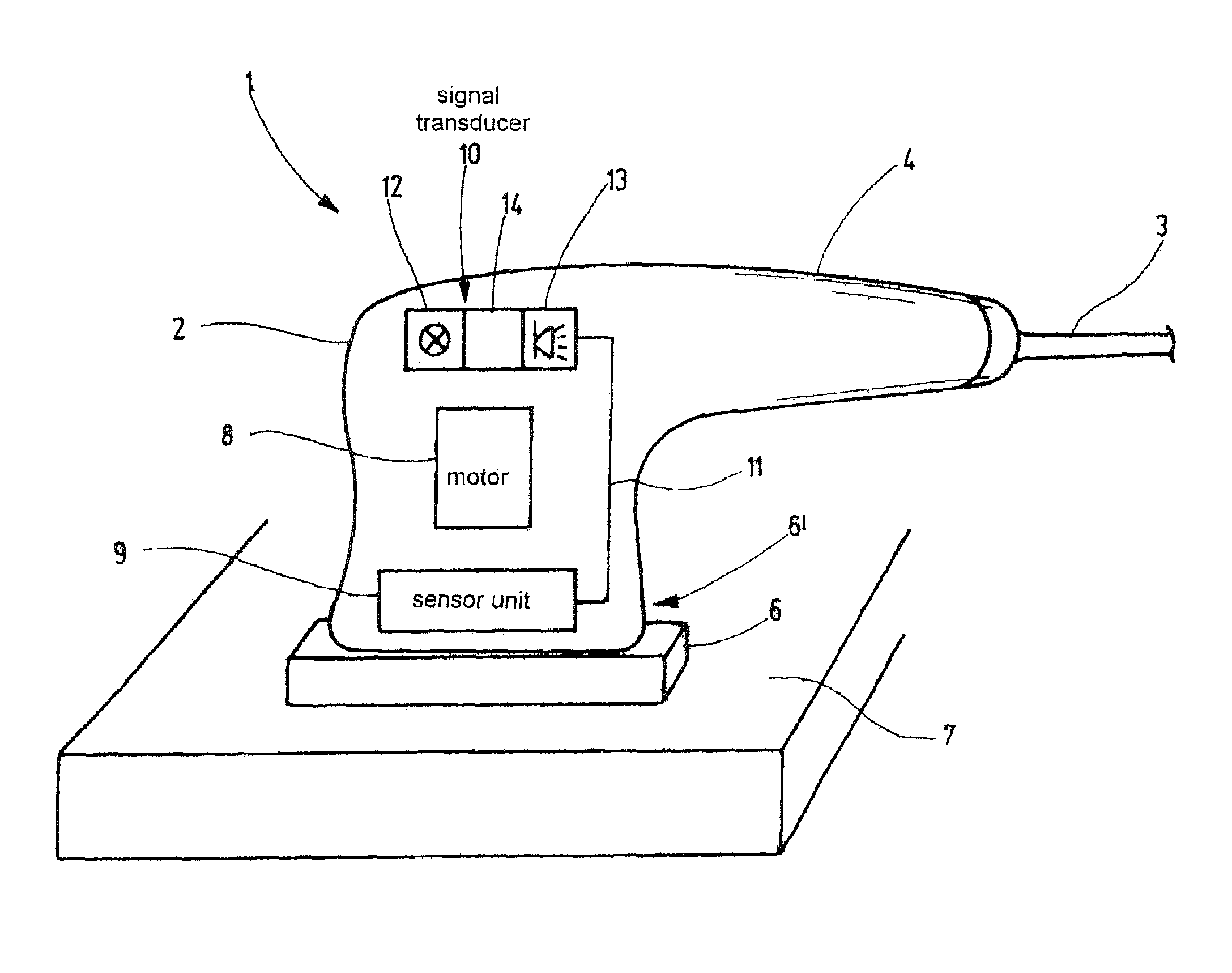
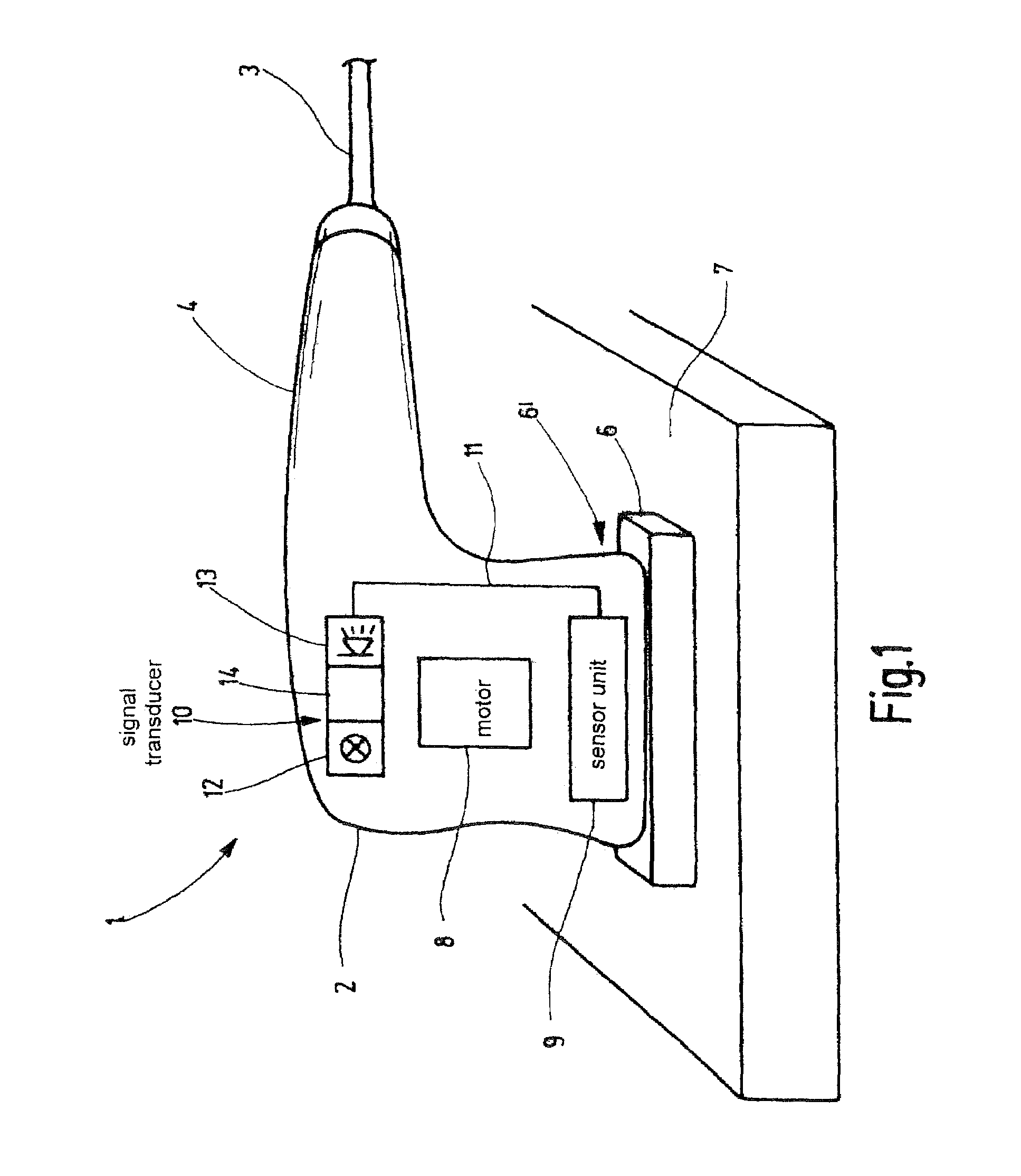
[0025]FIG. 1 shows an electric power tool 1, which is embodied as an eccentric grinder. It has a housing 2, an electrical supply cable 3, and a handle 4. FIG. 1 also shows a tool receptacle 6′ with a tool 6, with which a workpiece 7 can be machined. The drive of the tool 6 is done by an electric motor 8. The electric motor 8, operating at a certain rpm and with a corresponding torque, drives the tool 6, embodied as an abrasive substrate. Depending on the embodiment of the electric power tool 1, either a fixed rotary speed is specified, or different values for the rotary speed can be set. In the electronically regulated electric power tools, the rotary speed, once set, is kept constant during the work process, or in other words under load. A sensor unit 9 ascertains the contact pressure of the tool 6 against the workpiece 7 that the user exerts in handling the electric power tool 1. The sensor unit 9 has a strain gauge, not shown in the drawing, or—in an alternative exemplary embodim...


PUM


Abstract

The invention relates to an electric power tool (1), having an electric motor (8) that serves to drive a tool (6). The electric power tool (1) is characterized in that a sensor unit (9) that detects the contact pressure of the tool (6) against a workpiece (7) cooperates with a signal transducer (10).

Description

[0001]The invention relates to electric power tools and to methods for guiding the operation of electric power tools.PRIOR ART[0002]Electric power tools are known, for example in the form of power drills, drilling screwdrivers, power grinders, and eccentric grinders. These electric power tools in general have a rotatable receptacle for a tool. The tool receptacle is driven by an electric motor. Simple versions of electric power tools have a fixed rotary speed specified for idling. Somewhat better versions of electric power tools have the capability, depending on the application, that a different rotary speed can be set. In electronically regulated electric power tools, this rotary speed, once set during idling, is kept constant during the work, or in other words under load. In the work process, the user presses the electric power tool with its tool against the object to be machined. In the case of an eccentric grinder, a grinding substrate for instance forming the tool is pressed ag...

Claims


Application Information

Patent Timeline
Patent Type & Authority Patents(United States)
IPC IPC(8): H02P29/00B24B23/00B24B23/04B24B49/16B25F5/00
CPCB24B23/04B24B49/16B25F5/00B25F5/021Y10S388/937
Inventor SIEBER, GUSTAVSINGLE, ULRICH
Owner ROBERT BOSCH GMBH
Why Eureka
Try Eureka