Axial elastic force-applying connection method for electric connector contact pair
A technology of electrical connectors and contact pairs, applied in the direction of contact parts, etc., can solve problems such as connection failure, small contact surface, and reduced reliability, and achieve the effects of improved service life, small contact resistance, and high reliability
- Summary
- Abstract
- Description
- Claims
- Application Information
AI Technical Summary
Problems solved by technology
Method used
Image
Examples
Embodiment 1
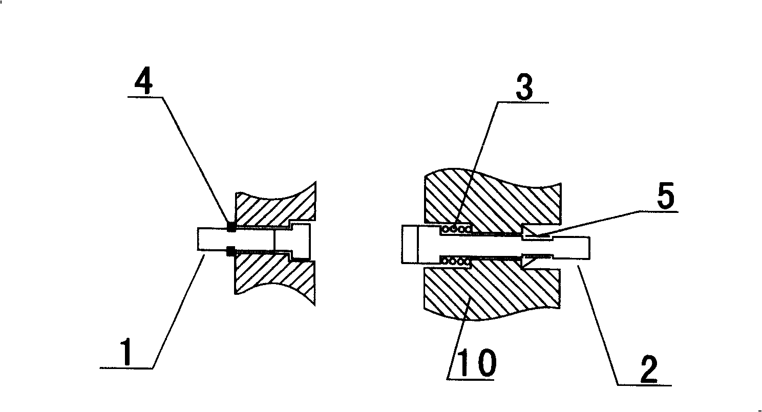
[0052] Such as figure 1 As shown: the electrical connector is connected to the device with elastic force in the axial direction. The contact A (1) connected to the end face of the contact pair is in the shape of "T", and one end passes through the insulator (10). The contact cavity is fixed by the elastic positioning element ( 4) Fixed, the other end surface is in contact with the end surface of the contact piece B (2); the contact piece B (2) passes through the spring (3) and the insulator (10) in a "T" shape. ) fixed, the insulator contact cavity is suitable for the contact shape.
[0053] When the end surfaces of the insulators are connected under the action of the connecting force of the shell, the contact piece A (1) remains stationary, and the contact piece B (2) is force-oriented after contacting with the contact surface of the contact piece A (1) After the movement, under the reaction force of the elastic element spring (3), the conduction connection between the conta...
Embodiment 2
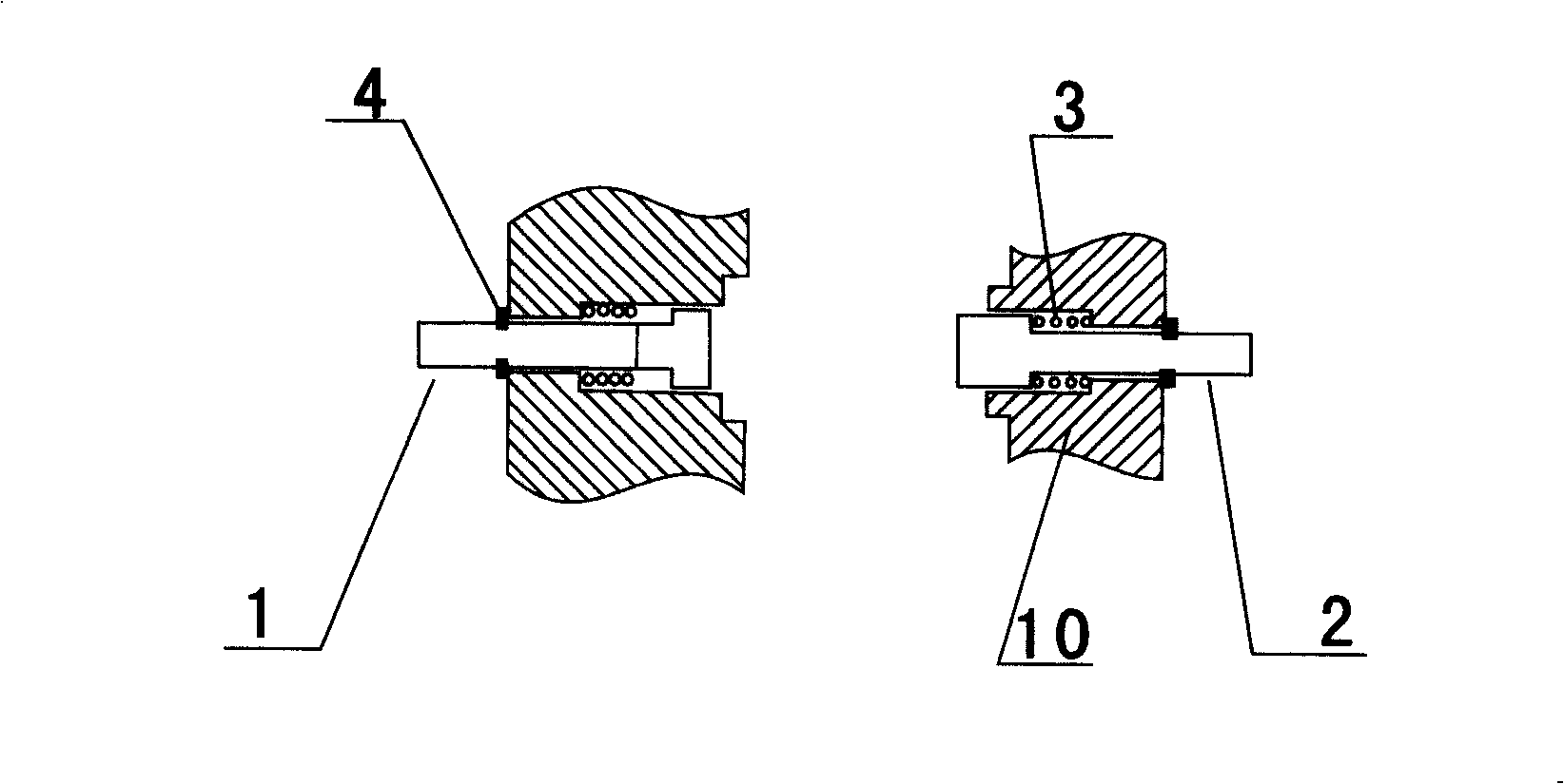
[0055] Such as figure 2 Shown: The electrical connector is a device for connecting the contact pair to the axial elastic force, and the contact pair end face connection can also be made by the contact piece A (1) passing through the spring (3) and the insulator (10) in a "T" shape. The cavity is fixed by the elastic positioning element (4), and the other end surface is in contact with the end surface of the contact piece B (2); the contact piece B (2) passes through the spring (3) in the shape of a "T", and the contact cavity of the insulator (10) is formed by The elastic positioning element (4) is fixed, and the cavity of the contact part of the insulator is made into a shape suitable for the contact part.
[0056] When the end surfaces of the insulators meet under the action of the coupling force of the shell, the contact A (1) and the contact B (2) are contacted because the contact surfaces are connected, and the contact A (1) and the contact B (2) are respectively stresse...
Embodiment 3
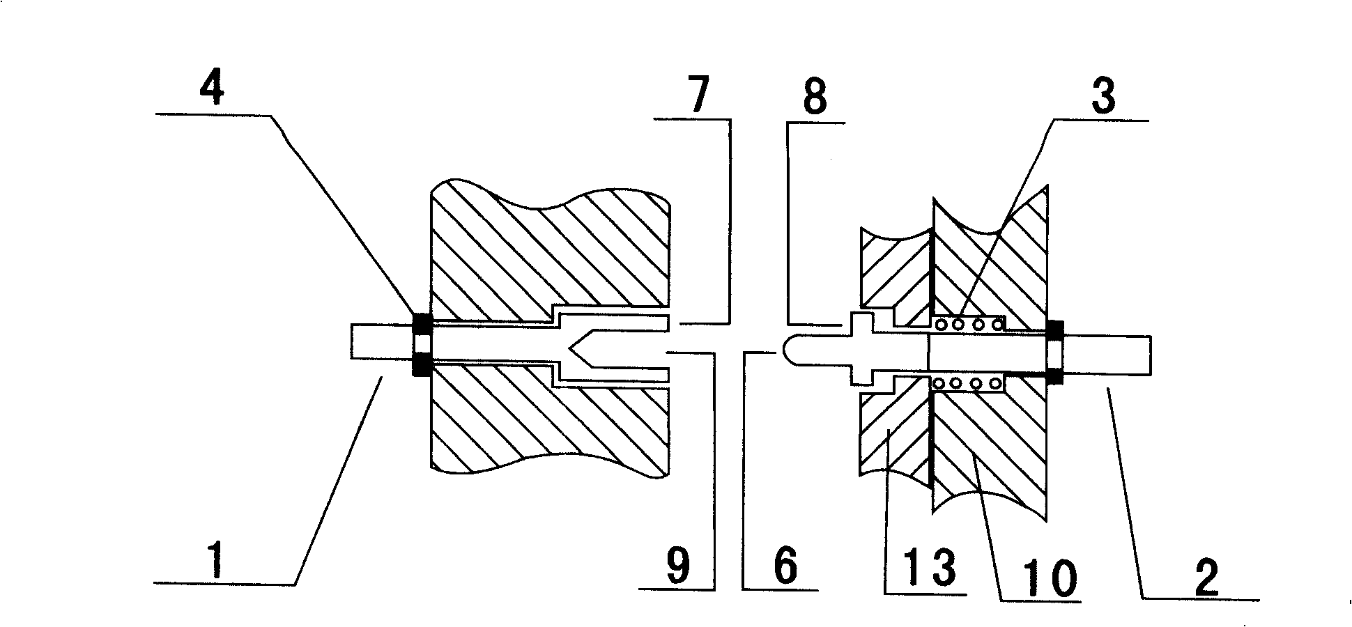
[0058] Such as image 3 Shown: The electrical connector is a device that connects the contact pair with axial elastic force. The connection method of the conductive contact pair adopts the contact pair plug-in end face connection. 10) The cavity of the contact piece is fixed by the elastic positioning element (4), and the other end is set in a hole shape, and the surface of the socket (9) and the end surface (7) of the hole are in contact with the pin (6) of the contact piece B (2); the contact piece A contact table end surface (8) is arranged on the B (2) pin, and the other end passes through the baffle plate (13), the spring (3), the insulator (10) and the contact cavity and is fixed by the elastic positioning element (4). Figure 4.1 yes image 3 Structural diagram of contacts A and B rotated by 90°.
[0059] When the end surfaces of the insulators meet under the action of the coupling force of the housing, the contact piece A (1) remains stationary, the pin (6) of the co...
PUM
 Abstract
Description
Claims
Application Information
 - R&D
- Intellectual Property
- Life Sciences
- Materials
- Tech Scout
- Unparalleled Data Quality
- Higher Quality Content
- 60% Fewer Hallucinations
Browse by: Latest US Patents, China's latest patents, Technical Efficacy Thesaurus, Application Domain, Technology Topic, Popular Technical Reports.
© 2025 PatSnap. All rights reserved.Legal|Privacy policy|Modern Slavery Act Transparency Statement|Sitemap|About US| Contact US: help@patsnap.com


