Recessed belt damper

Active Publication Date: 2009-01-01
DAYCO IP HLDG
View PDF22 Cites 30 Cited by
  • Summary
  • Abstract
  • Description
  • Claims
  • Application Information

AI Technical Summary

Benefits of technology

[0007]The present invention is premised on the realization that a torsional vibration damper can be designed wherein relatively high slip torque or contact pressures can be achieved without creating high strains on the elastomeric member. The torsional vibrations of the present invention include a channel that receives a portion of the elastomeric member with a portion of the

Problems solved by technology

The torsional vibrations may have a considerable amplitude and, if not abated, can potentially damage gears or similar structures attached to the rota

Method used


Image

  • Recessed belt damper
  • Recessed belt damper
  • Recessed belt damper

Examples


Example

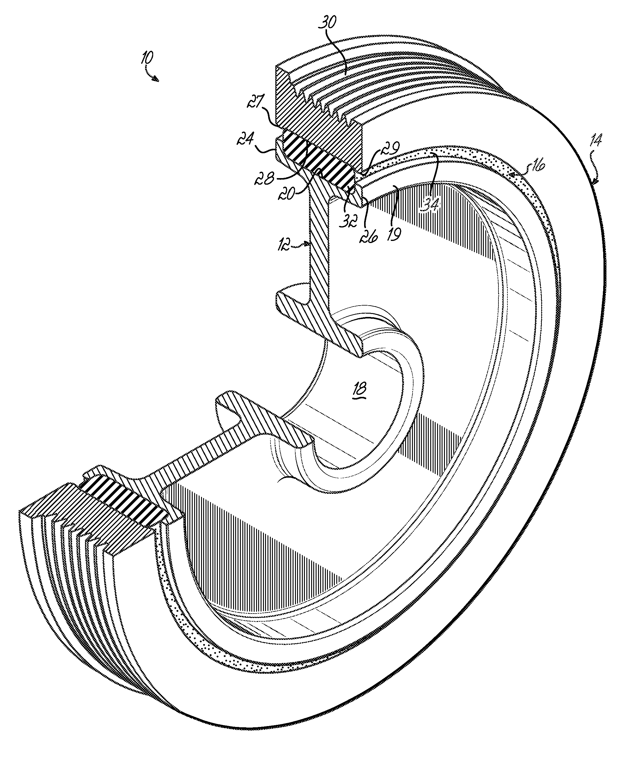
[0014]As shown in FIG. 1, a crankshaft torsional vibration damper 10 includes a central hub member 12 and an annular inertia mass 14 separated by an elastomeric vibration absorbing member 16. This can be a continuous ring or an annular strip and is simply referred to as ring 16.

[0015]The central hub member 12 includes a central opening 18 which is adapted to attach to the crankshaft. Further, the hub member 12 includes a peripheral rim 19. The rim 19 includes a channel 20 having first and second side walls 24 and 26.

[0016]In turn, the inertia mass 14 has an interior annular surface 28 and an exterior surface 30. The exterior surface 30 in this embodiment is configured to engage a serpentine belt (not shown). However, in other embodiments a serpentine belt may not be employed. The side edges 27 and 29 of surface 28 are raised slightly about 0.5 mm, leaving a gap between the rim 19 and surface 28 of about 1.1 mm.

[0017]The elastomeric ring 16 includes a portion 32 which is located in c...


PUM


Abstract

A torsional vibration damper includes an inertia mass and a rotating shaft or hub with an elastomeric ring between the inertia mass and the rotating shaft or hub. A large portion of said elastomeric member is located in a channel located either in the inertia mass or in the hub. This allows one to achieve high contact pressure without creating a significant fatigue on the elastomeric member. This can be used with either a crankshaft damper or an internal or external drive shaft damper.

Description

FIELD OF THE INVENTION[0001]The invention relates to torsional vibration dampers and, in particular, to vibration dampers adapted to be mounted to rotatable shafts such as the crankshaft or drive shaft of an internal combustion engine.BACKGROUND OF THE INVENTION[0002]Torsional vibration dampers are employed extensively in internal combustion engines to reduce torsional vibrations delivered to rotatable shafts. The torsional vibrations may have a considerable amplitude and, if not abated, can potentially damage gears or similar structures attached to the rotatable shaft and cause fatigue failure of the rotatable shaft. Torsional vibration dampers absorb vibration and, to a certain extent, reduce the amplitude of the vibrations by converting the vibrational energy to thermal energy as a result of the damping action. The absorption of the vibrational energy lowers the strength requirements of the rotatable shaft and, therefore, lowers the required weight of the shaft. The torsional vib...

Claims


Application Information

Patent Timeline
IPC IPC(8): F16F15/12F16F7/104
CPCF16F7/108Y10T74/2131Y10T74/2121F16F15/126F16F15/10
Inventor CHRISTENSON, BRUCE G.MANZOOR, SUHALE
Owner DAYCO IP HLDG
Why Eureka
Try Eureka