Connection-switch arrangement

a technology of switch arrangement and connection, which is applied in the direction of coupling device connection, coupling device details, two-pole connection, etc., can solve the problems of high resistance between and excessive beam stress, and achieve the effect of reducing beam deflection, high contact pressure, and high contact pressur

Inactive Publication Date: 2005-04-19
ITT MFG ENTERPRISES LLC
View PDF11 Cites 32 Cited by
  • Summary
  • Abstract
  • Description
  • Claims
  • Application Information

AI Technical Summary

Benefits of technology

[0004]In accordance with one embodiment of the present invention, a connection / switch arrangement is provided, in which a first connector in the form of a receptacle has an opening that can receive a second connector, or actuator, in the form of a plug. When the plug is received, an inner contact of the plug contacts and downwardly deflects a beam until the plug is fully installed in the receptacle. The present system minimizes deflection of the beam and assures high pressure contact between the plug inner contact and beam. A stop lying under the beam, limits downward deflection of the beam, which assures high contact pressure with small beam deflection. The plug inner contact can slide upward with respect to the plug frame against the resilience of a spring. Accordingly, when the plug is pushed down, the plug inner contact depresses the beam against the stop, and the plug frame can continue to move down slightly while the plug inner contact is stopped.

Problems solved by technology

One disadvantage of this arrangement is that there is only moderate pressure between the inner contact of a plug and the beam, which can result in high resistance between them.
Also, to obtain even moderate force between the plug inner contact and the beam, the beam should be deflected considerably, which can require a longer beam or which can result in excessive stress on the beam.

Method used


Image

  • Connection-switch arrangement
  • Connection-switch arrangement
  • Connection-switch arrangement

Examples


Embodiment Construction

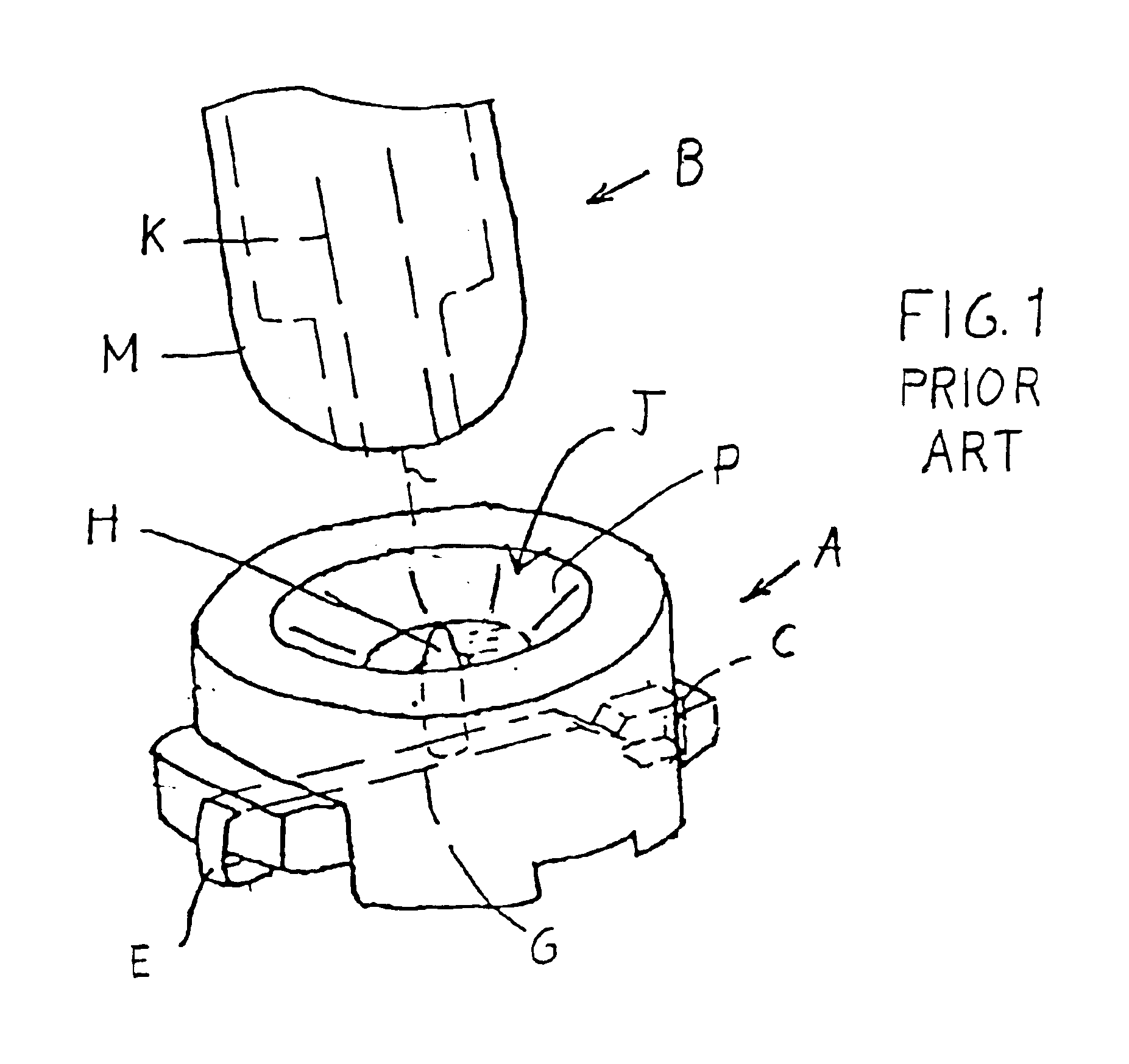
[0013]FIG. 1 shows a prior art connector assembly, which includes a first connector / switch or receptacle A, which is usually mounted on a circuit board, and a second connector or plug B. The receptacle has first and second contacts C, E, with the first contact having a beam G that is normally engaged with the second contact E. A projection H projects upwardly from a location on the beam G. When the plug B is pushed down into an entrance J of the receptacle, an inner contact K of the plug engages the upward projection H on the beam, and downwardly deflects the projection and beam. Such downward deflection continues until an outer contact M of the plug engages an outer contact P of the receptacle. It is difficult to assure high pressure contact between the plug inner contact K and projection H.

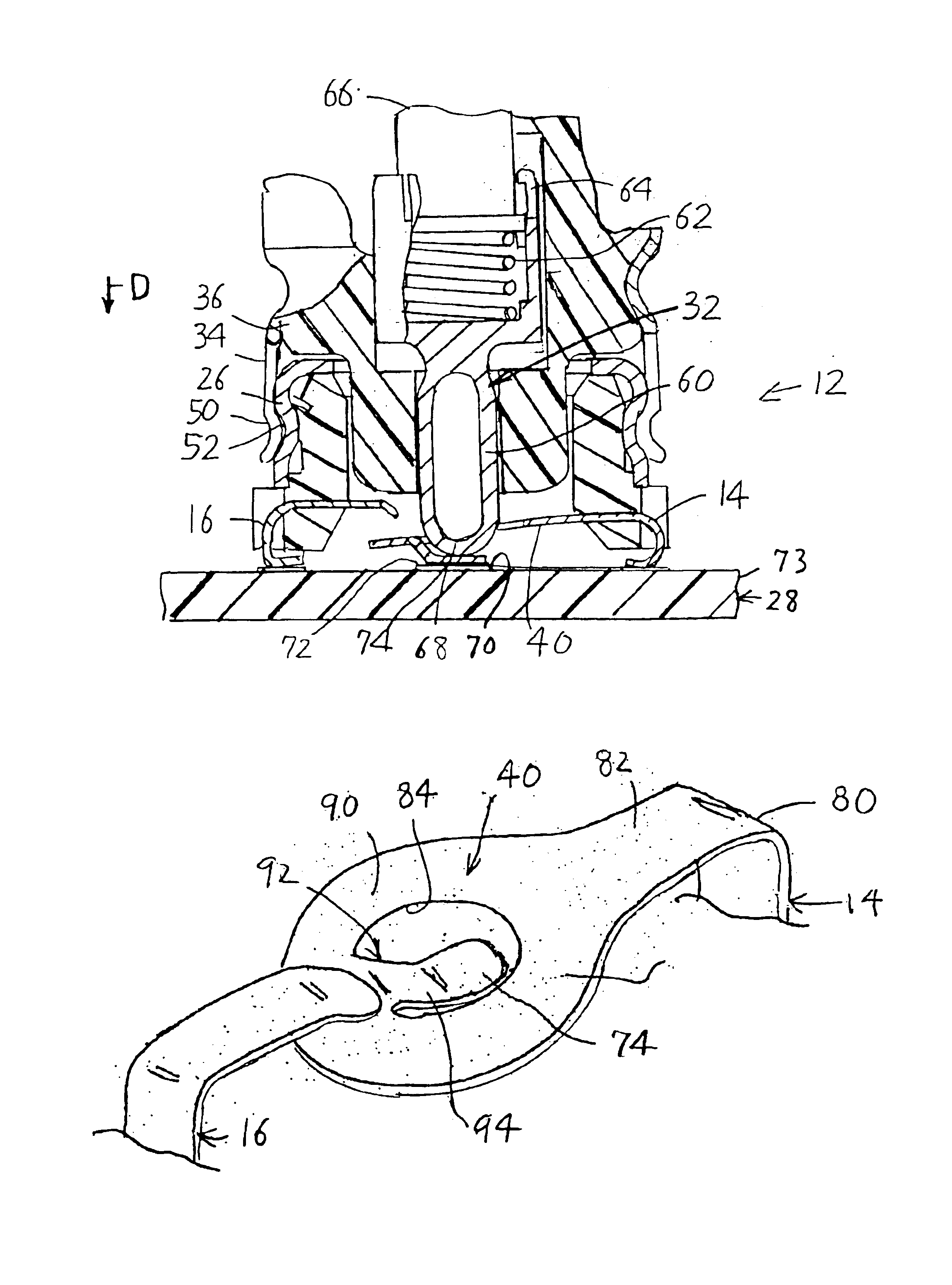
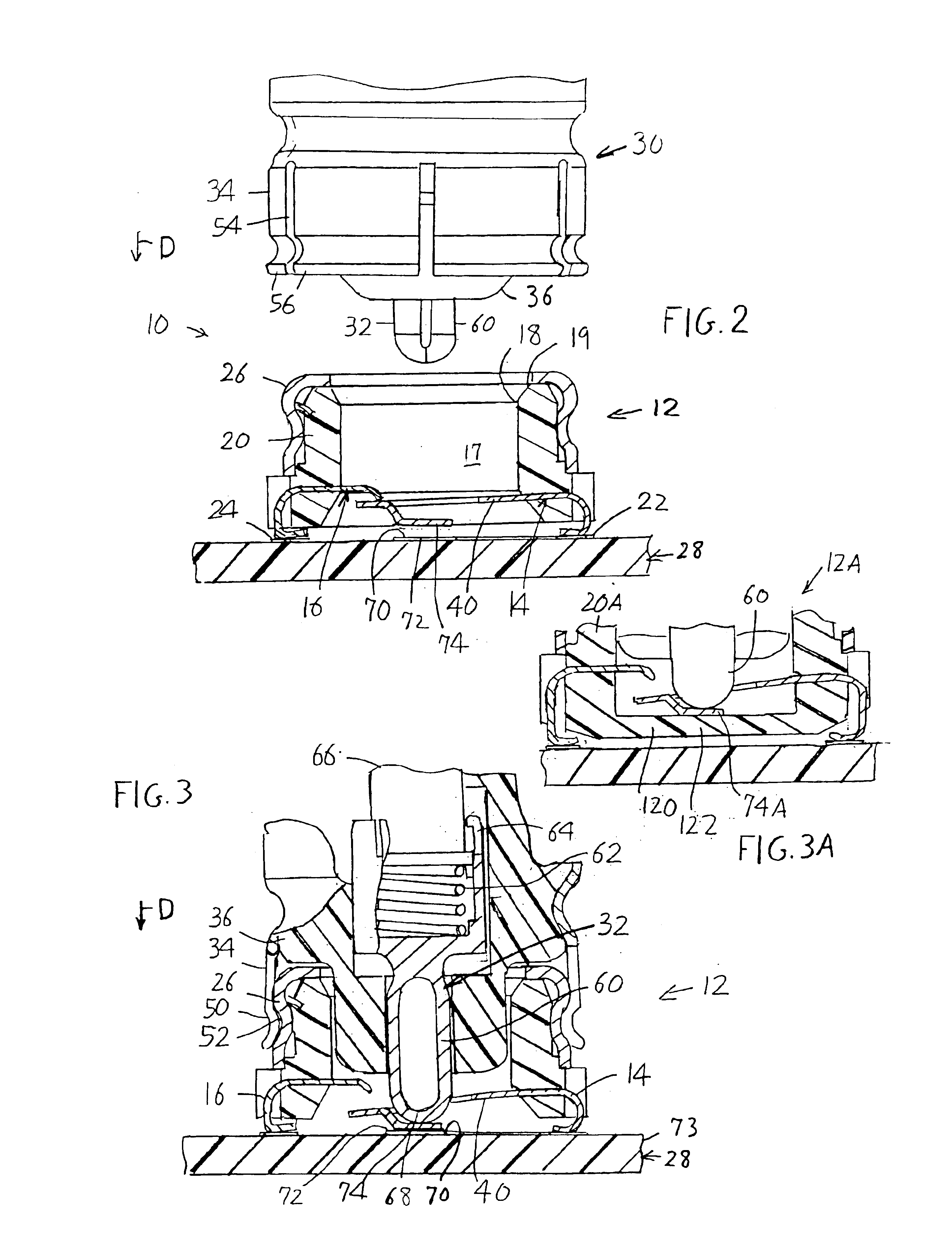
[0014]FIG. 2 illustrates a connection arrangement 10 of the present invention, which includes a first connector 12 that also operates as a switch and which can be referred to as a receptacle, th...


PUM


Abstract

A connection arrangement includes a first connector (12) with an opening leading to first and second contacts (14, 16), where the first contact includes a beam (40) that is biased upwardly against the second contact but which can be depressed out of engagement with the second contact. The beam is depressed by a plug inner contact (32) of a mating second connector (30) that passes into the opening and depresses the beam, in an arrangement that assures firm engagement of the plug inner contact with the beam despite small beam movement. A stop (70) lying under the beam, limits its downward movement by the plug inner contact. The plug inner contact is spring biased downwardly with respect to the second connector frame (36) but can move up, so the second connector can continue to move down a short distance after the plug inner contact has pushed the beam against the stop, to enable-full engagement of largely coaxial outer contacts (26, 34) of the first and second connectors. The arrangement enables reduced downward movement of the beam while assuring considerable pressure contact between the plug inner contact and beam.

Description

CROSS-REFERENCE[0001]Applicant claims priority from United Kingdom patent application GB 0216111.5 filed Jul. 11, 2002.BACKGROUND OF THE INVENTION[0002]U.S. Pat. No. 6,439,906 describes a coaxial connector system in which a first connector has a first contact with a beam that is upwardly biased against a second contact. When a second connector, or plug, is pushed toward the first connector, a plug inner contact pushes down the beam and deflects it out of engagement with the second contact. This arrangement not only opens one circuit, between the first and second contacts, and closes another circuit, between the first contact and the plug inner contact, but enables the plug to be pushed down sufficiently for outer coaxial contacts to fully engage one another. One disadvantage of this arrangement is that there is only moderate pressure between the inner contact of a plug and the beam, which can result in high resistance between them. Also, to obtain even moderate force between the plu...

Claims


Application Information

Patent Timeline
Patent Type & Authority Patents(United States)
IPC IPC(8): H01R13/703H01R13/00H01R13/646H01R13/70H01R29/00
CPCH01R13/7033H01R24/46Y10S439/944H01R2103/00H01R2201/16H01R29/00H01R13/6277
Inventor JORDAN, PETERGRAY, IAN JAMES STAFFORD
Owner ITT MFG ENTERPRISES LLC
Why Eureka
Try Eureka