Evaluation electronics system for a rotation-rate sensor

Inactive Publication Date: 2010-05-20
ROBERT BOSCH GMBH
View PDF5 Cites 18 Cited by
  • Summary
  • Abstract
  • Description
  • Claims
  • Application Information

AI Technical Summary

Benefits of technology

[0013]According to one additional refinement, the evaluation electronics system is developed for ascertaining an acceleration acting on the rotati

Problems solved by technology

The measurement of the rotation rate acting on t

Method used


Image

  • Evaluation electronics system for a rotation-rate sensor
  • Evaluation electronics system for a rotation-rate sensor
  • Evaluation electronics system for a rotation-rate sensor

Examples


Embodiment Construction

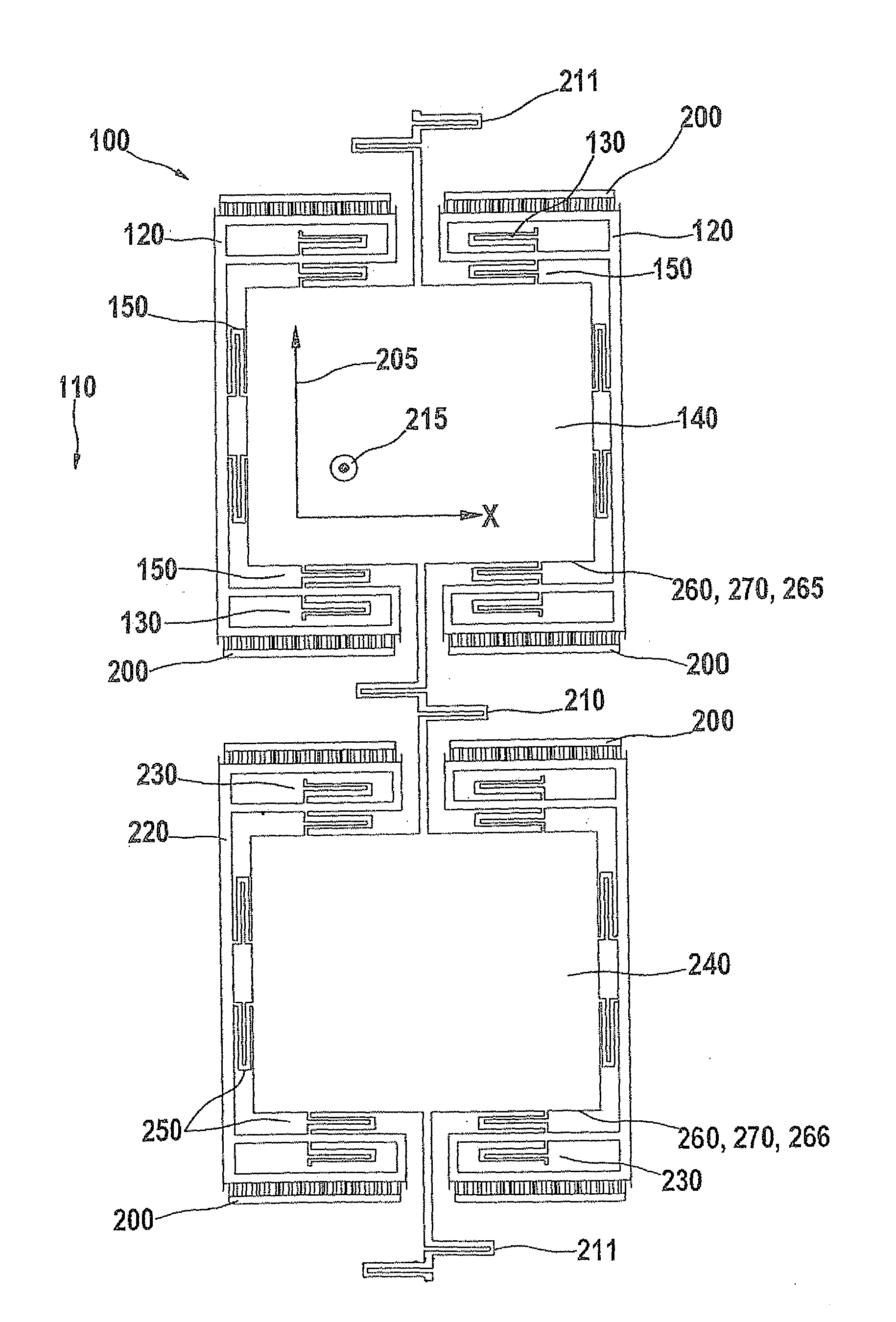
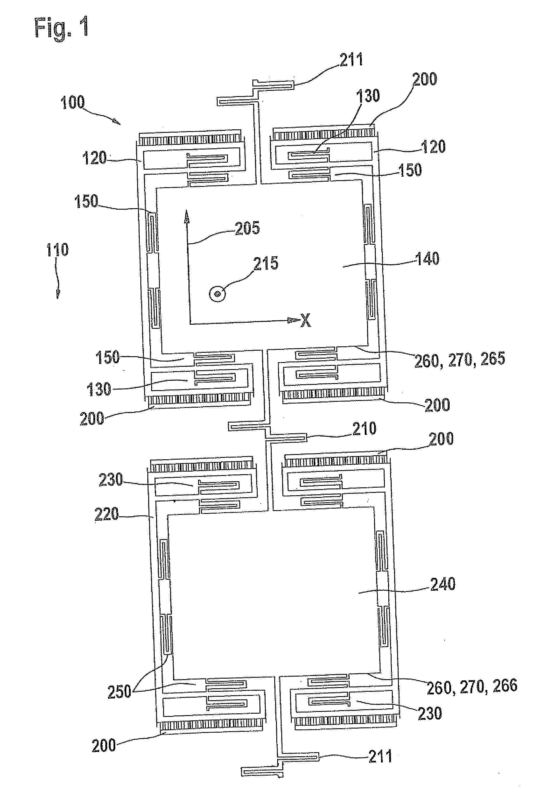
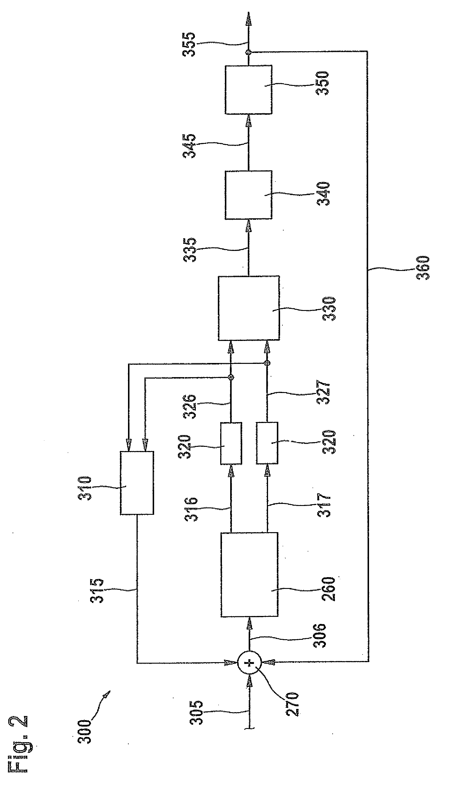
[0016]FIG. 1 shows a schematic top view onto a micromechanical rotation-rate sensor 100, which is able to be used together with an evaluation electronics system 300, shown in FIG. 2. However, rotation-rate sensor 100 shown in FIG. 1 only represents an example. An evaluation electronics system 300 of FIG. 2 is suitable for use with any type of vibrating rotation-rate sensors. In particular, an evaluation electronics system 300 may also be used in connection with rotation-rate sensors that are provided for the detection of rotation rates about other rotational axes than the one in FIG. 1.

[0017]Rotation-rate sensor 100 is situated above a surface of a substrate 110. Substrate 110 may be a silicon substrate, for example. The surface of substrate 110 is situated in a plane that is generated by an x direction and a drive direction 205 perpendicular to it. A measuring direction 215 is oriented perpendicular to the substrate surface, that is, also perpendicular to the x direction and drive ...


PUM


Abstract

An evaluation electronics system for a rotation-rate sensor, having a first and a second seismic mass, is developed for the purpose of ascertaining a rotation rate, acting on the rotation-rate sensor, from a deflection of the first and second seismic masses. The evaluation electronics system, in this instance, has a regulation member in order to minimize an undesired deflection of the first and second seismic masses, caused by interference influences.

Description

BACKGROUND INFORMATION[0001]Rotation-rate sensors for ascertaining rotation rates, about one or more measuring axes, are known from the related art. In known micromechanical rotation-rate sensors, two or more seismic masses are driven in such a way that they execute an antiparallel vibration. If a rotation rate occurs about a stipulated measuring axis, the seismic masses are deflected in an antiparallel manner by Coriolis forces, perpendicular to the drive direction. These deflections are detected using an evaluation electronics system, and they supply a measure for the rotation rate that is to be measured.[0002]In rotation-rate sensors according to the related art, the sensitivity of the rotation-rate sensors to vibrations in the deflection direction of the seismic masses is observed in a frequency range of a few Hz up to a few kHz. An external vibration causes a motion of the seismic masses at the frequency of the external spurious response. The measurement of the rotation rate ac...

Claims


Application Information

Patent Timeline
IPC IPC(8): G01C19/56
CPCG01C19/574G01C19/5726
Inventor NEUL, REINHARDBALSLINK, THORSTEN
Owner ROBERT BOSCH GMBH
Why Eureka
Try Eureka