Air cleaner assembly and filter element providing improved dynamic wall stiffness

a filter element and air cleaner technology, applied in the field to achieve the effect of reducing wall nois

Inactive Publication Date: 2016-06-07
MANN HUMMEL GMBH
View PDF23 Cites 15 Cited by
  • Summary
  • Abstract
  • Description
  • Claims
  • Application Information

AI Technical Summary

Benefits of technology

[0007]It is an objective of the present inventive disclosure to provide an air cleaner assembly configured to reduce wall noise.
[0008]It is another objective of the present inventive disclosure to provide an air cleaner assembly that reduces wall noise by rigidly coupling the movement of opposing air cleaner housing side walls through the filter element installed into the air cleaner housing. This is particularly advantageous as, for example, a pressure increase in the air cleaner housing may tend to deflect opposing sidewalls outwardly and in opposite directions. However, when the sidewalls are rigidly coupled through the filter element then the wall deflection forces created by the pressure increase tend to cancel each other through the rigid coupling provided through the filter element. Further details of how this is accomplished are provided herein.
[0010]The air cleaner assembly includes an air cleaner housing having separable first housing and second housing shells. The first and second housing shells are separable for installation and removal of the filter element for service. Secured to opposing sidewalls of at least one housing shell is a plurality of locking receptacles configured to demountably and lockably engage the locking members of the filter element. The lockable engagement rigidly and detachably couples the opposing sidewalls of the housing shells through the stiffening members of the filter element. The rigid coupling provides dynamic stiffening of the sidewalls through the stiffening members of the filter element. The dynamic wall stiffening through the filter element provides reduced air cleaner housing wall noise by stiffening of the side walls against pressure pulsations present in an air stream in the air cleaner housing and minimizes wall deflections by coupling wall movements through the filter element so that pressure pulsation forces on opposing air cleaner housing walls tend to cancel through the stiffening members.
[0012]According to another aspect of the invention, the locking member includes at least one tab member provided on both opposing ends of the locking members. Locking receptacles are provided on and secured to opposing sidewalls of both housing shells. The locking receptacles are positioned to lockably engage with the tab members of the locking members of the filter element to dynamically couple the opposing housing walls and provide dynamic stiffening of the walls.
[0014]According to another aspect of the invention the opposing end of the locking members are provided with two tab members spaced apart to form a notch therebetween. The two tab members with the notch are provided on and extend axially outwards from at least one end of the locking members. The locking receptacles include a tongue member positioned in the receptacle gap between the wall members with the tongue member received into the notch between the two tab members of the locking member. The tongue member engaging the notch prevents movement of the locking member relative to the locking receptacle in a third direction aligned with the receptacle gap.
[0015]According to another aspect of the invention the locking receptacles are provided on the sidewalls of both the first and second housing shells and tab member are provided on both ends of the locking members. The engagement of the locking members at the opposing ends into the locking receptacles of the first and second housing shells prevents movement of the locking members relative to the locking receptacles in a direction aligned with an opening direction of the air cleaner housing.

Problems solved by technology

However, when the sidewalls are rigidly coupled through the filter element then the wall deflection forces created by the pressure increase tend to cancel each other through the rigid coupling provided through the filter element.

Method used


Image

  • Air cleaner assembly and filter element providing improved dynamic wall stiffness
  • Air cleaner assembly and filter element providing improved dynamic wall stiffness
  • Air cleaner assembly and filter element providing improved dynamic wall stiffness

Examples


Embodiment Construction

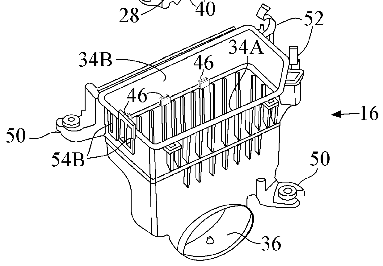
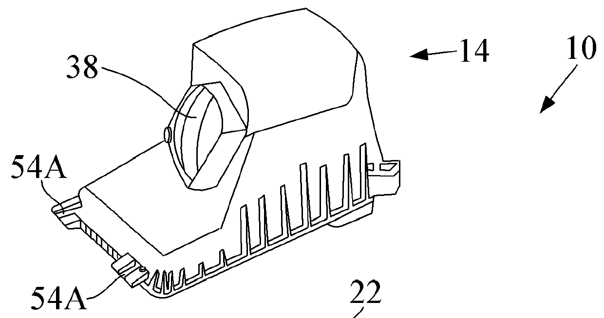
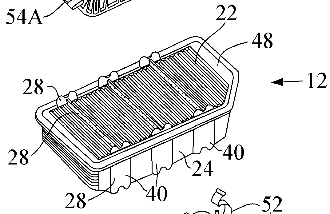
[0031]Before describing in detail embodiments that are in accordance with the present invention, it should be observed that the embodiments reside primarily in combinations of apparatus components related to the reduction of air cleaner housing wall noise by providing dynamic wall stiffening components integrated with the replaceable filter element. Accordingly, the apparatus components have been represented where appropriate by conventional symbols in the drawings, showing only those specific details that are pertinent to understanding the embodiments of the present invention so as not to obscure the disclosure with details that will be readily apparent to those of ordinary skill in the art having the benefit of the description herein.

[0032]In this document, relational terms such as first and second, top and bottom, and the like may be used solely to distinguish one entity or action from another entity or action without necessarily requiring or implying any actual such relationship...


PUM

PropertyMeasurementUnit
dynamic wall stiffnessaaaaaaaaaa
pressure pulsationsaaaaaaaaaa
pressureaaaaaaaaaa

Abstract

An air cleaner assembly and a filter element reduce wall noise by rigidly coupling the movement of opposing air cleaner housing sidewalls through the installed filter element. The sidewalls are rigidly coupled through the filter element with the sidewalls coupled to move together in unison such that wall deflection forces created by the pressure pulsations tend to cancel each resulting in improved dynamic stiffening of the air cleaner walls and reduced wall noise.

Description

CROSS REFERENCE TO RELATED APPLICATIONS[0001]This application is US National Stage Entry of international patent application no. PCT / EP2012 / 050306, filed Jan. 10, 2012 designating the United States of America, the entire disclosure of which is incorporated herein by reference. PCT / EP2012 / 050306 claims priority to U.S. provisional patent application No. 61 / 431,461 filed Jan. 11, 2011.TECHNICAL FIELD[0002]The present disclosure relates to air induction systems for internal combustion engines and, more particularly, to apparatus and methods of reducing wall noise in air cleaner housings installed in air induction systems.BACKGROUND OF THE INVENTION[0003]To reduce component costs and remove weight from the vehicle, air induction systems may be comprised of relatively lightweight and somewhat flexible molded plastic ducts and air cleaner housings (also known as air filter housings). Air cleaner housings may have comparatively large substantially flat sidewalls that are particularly sensi...

Claims


Application Information

Patent Timeline
Patent Type & Authority Patents(United States)
IPC IPC(8): B01D50/00B01D46/10F02M35/14B01D49/00B01D46/00B01D41/00B01D39/00B01D51/00B01D46/42F02M35/024B01D46/52F02M35/02
CPCF02M35/14B01D46/0002B01D46/10B01D46/4236B01D46/521F02M35/0245F02M35/02425F02M35/02491F02M35/0203B01D46/52F02M35/024
Inventor OH, DAL JIN
Owner MANN HUMMEL GMBH
Why Eureka
Try Eureka