Eureka AIR delivers breakthrough ideas for toughest innovation challenges, trusted by R&D personnel around the world.

Method of making a gas turbine engine diffuser

Inactive Publication Date: 2006-10-03
PRATT & WHITNEY CANADA CORP
View PDF4 Cites 17 Cited by
  • Summary
  • Abstract
  • Description
  • Claims
  • Application Information

AI Technical Summary

Benefits of technology

[0012]One object of the present invention is to provide an improved method of machining diffuser bores in a gas turbine engine diffuser ring which minimizes tool deflection.
[0013]Another object of the present invention is to provide a method of machining diffuser bores in a gas turbine engine diffuser ring which improves the surface finish of the diffuser bores.
[0017]The method according to the present invention, when being used to machine diffuser bores in a gas turbine engine diffuser ring, advantageously reduces manufacturing costs by providing improved quality of position and diameter, thereby eliminating scraps and deviations. Manufacturing costs are further reduced by the reduction in machining time and lead-time, which increases productivity. Furthermore, the method of machining diffuser bores in a gas turbine engine diffuser ring according to the present invention provides a better surface finish of the diffuser bores and a better repeatability of the turbine engine diffuser rings, which both improve turbine engine performance.

Problems solved by technology

For example, the orifices in the impeller surrounding ring are typically cylindrical bores or conical bores due to the limitations of economical drilling procedures.
To provide elliptical holes for example, would involve prohibitively high costs in preparation and quality control.
This makes the diffuser one of the most costly and difficult parts of the gas turbine engine to manufacture.
The two intersections of adjacent bores are not symmetrical, and therefore, the radial cutting force on the finishing tool is unbalanced, creating undesirable tool deflection, which results in poor quality of both position and diameter.
Furthermore, the unbalanced radial cutting force and the tool deflection inhibit the use of carbide tools which are adapted for high speed cutting but are too brittle to handle tool deflections normal in this type of operation.
Thus, productivity of the diffuser bore machining process is limited.
The conventional process also cannot provide a superior quality of surface finishing of the diffuser bores because the asymmetrical intersections of each diffuser bore limits the use of super-finishing tools such as burnishing tools.

Method used


Image

  • Method of making a gas turbine engine diffuser
  • Method of making a gas turbine engine diffuser
  • Method of making a gas turbine engine diffuser

Examples


Embodiment Construction

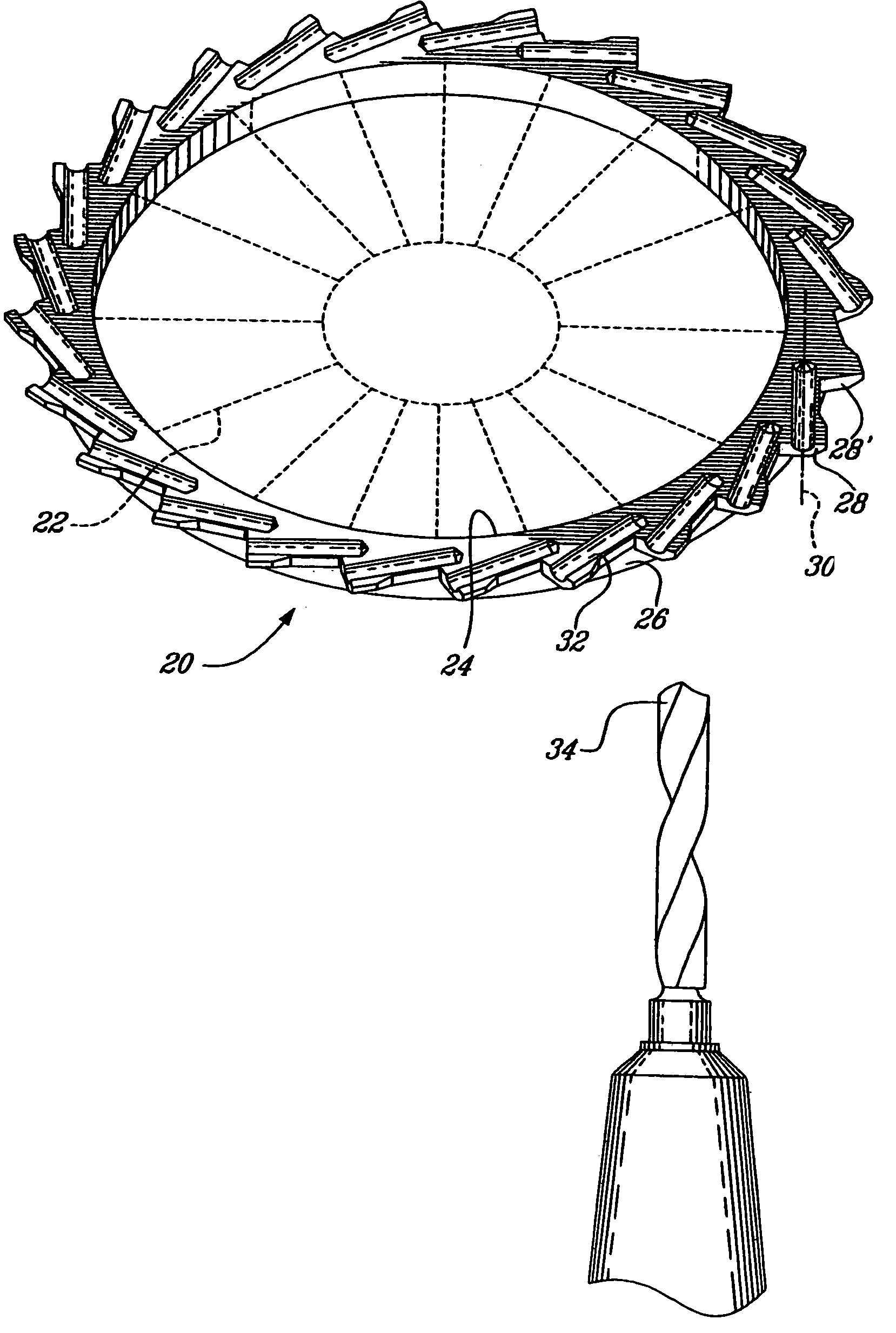
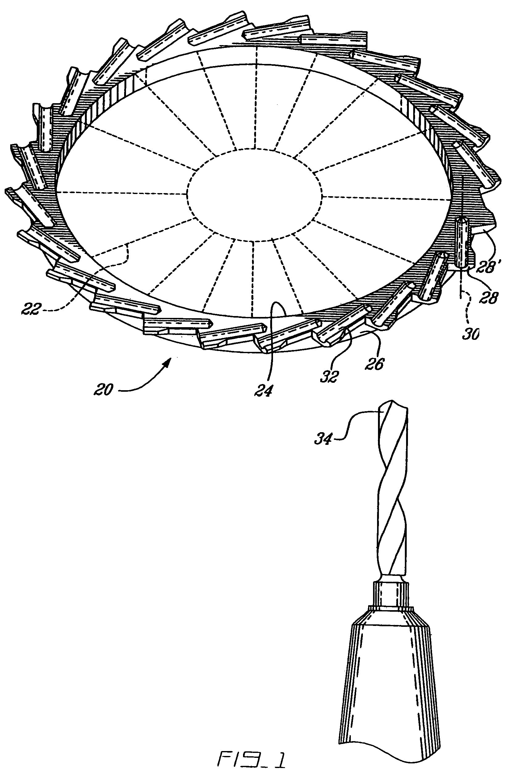
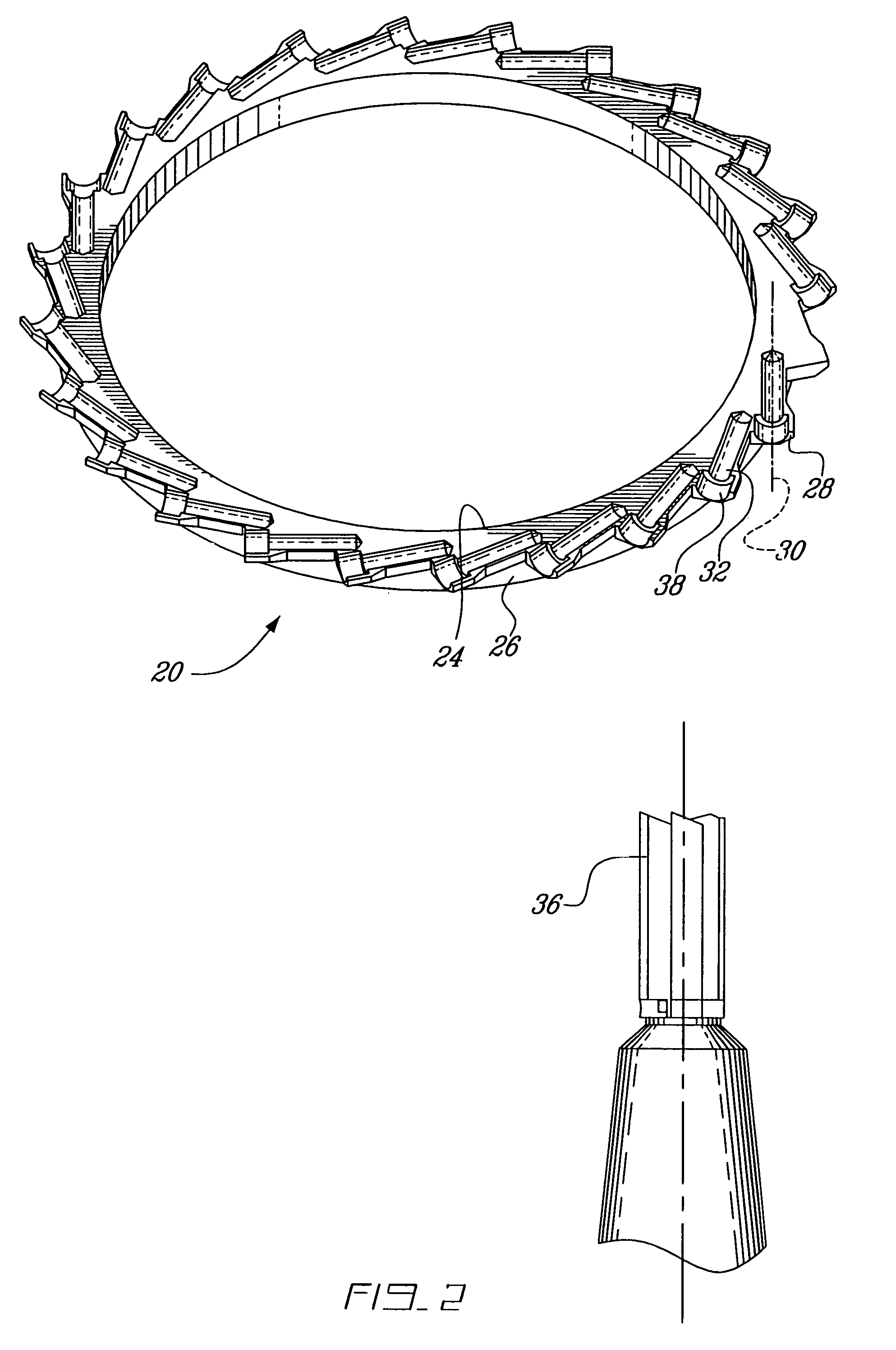
[0033]A process of machining a plurality of diffuser bores in a turbine engine diffuser ring of the general type described in U.S. Pat. No. 5,387,081, issued to LeBlanc on Feb. 7, 1995. incorporated herein by reference, is described step-by-step below. The diffuser bores are circumferentially and typically, equally spaced apart, and surround a turbine engine impeller in tangential positions when the diffuser ring is assembled with the impeller. Each diffuser bore is intersected by two adjacent diffuser bores in an asymmetrical configuration which will be more clearly described with reference to the drawings hereinafter. However, the example described below is illustrative of one use of the method according to the present invention. The invention need not necessarily be applied only to a diffuser ring of a gas turbine engine however, and may be applied to produce any object having bores extending circumferentially and generally inwardly, so that two adjacent bores intersect in an asy...


PUM


Abstract

A method of machining a plurality of intersecting bores in an object, the method comprising steps of machining a first bore, plugging the first bore, machining a second bore so as to intersect the first bore, and unplugging the first bore.

Description

CROSS-REFERENCED TO RELATED APPLICATION[0001]This application is a continuation of U.S. patent application Ser. No. 10 / 194,556, filed Jul. 15, 2002, now U.S. Pat. No. 6,760,971.FIELD OF THE INVENTION[0002]The invention relates to a gas turbine engine diffuser, and more particularly to a method of machining a gas turbine engine diffuser.BACKGROUND OF THE INVENTION[0003]The compressor section of a gas turbine engine includes a diffuser downstream of the compressor. The function of the diffuser is to reduce the velocity of the compressed air and simultaneously increase the static pressure, thereby preparing the air for entry into the combustor at a lower velocity. Presenting high-pressure and low-velocity air to the combustor section is essential for proper fuel mixing and efficient combustion.[0004]A centrifugal compressor impeller draws air axially, and rotation of the impeller increases the velocity of the air flow as the input air is directed over impeller vanes to flow in a radial...

Claims


Application Information

Patent Timeline
IPC IPC(8): B23P15/00B23B35/00B23P13/00B23P15/04B23B41/00F04D29/44
CPCB23B41/00F04D29/444Y10T29/4932Y10T29/49316Y10T29/49995Y10T408/03Y10T29/49996F05D2250/52
Inventor SASU, IOANGENDREAU, BERTRANDLANOUE, ROBERT FRANCOIS
Owner PRATT & WHITNEY CANADA CORP
Why Eureka
Eureka Blog
Learn More