Audio Equipment and Bracket for Linear Lighting Device Thereof

a technology of linear lighting and audio equipment, which is applied in the direction of lighting support devices, instruments, applications, etc., can solve the problems of not being suitable for use in audio equipment, and achieve the effects of reducing the noise caused by the light source on the outside of the housing, low cost, and long li

Inactive Publication Date: 2015-09-17
YAMAHA CORP
View PDF9 Cites 0 Cited by
  • Summary
  • Abstract
  • Description
  • Claims
  • Application Information

AI Technical Summary

Benefits of technology

[0007]According to the aforementioned audio equipment, because the light source is arranged inside the housing away from the opening, the influence of noise caused by the light source on the outside of the housing can be reduced. Although not necessarily limited to, an LED should preferably be adopted for the light source because of its low cost and long life. Considering the influence of noise, the configuration according to the invention is particularly effective for LED. Noted that, in the present specification, “linear” shape includes not only a long, rod-like shape having a round, rectangular, polygonal cross-sectional shape or the like but also a shape having a flat, strip-like cross-section as long as the length in a longitudinal direction is sufficient with respect to the cross-sectional shape and the shape is considered to be substantially linear. Further, the shape of the light guide member is not necessarily limited to straight shapes but also includes curved and bent shapes and the like. Also, when connecting light sources to both ends of the light guide member, the both ends of the light guide member shall be accommodated in the housing away from the opening.
[0008]In one embodiment, the light guide member may be formed by a flexible material. Accordingly, the light guide member can be bent at necessary locations when wired, and therefore routing of the light guide member is facilitated.
[0009]In one embodiment, an emission surface of the light source and an incident surface of the light guide member may be in surface contact with each other, and the light guide member may have a flexure portion formed by elastic deformation of the light guide member in order to generate a pressing force in a longitudinal direction of the light guide member directed from the incident surface toward the emission by the flexure portion. According to the embodiment, by forming a flexure portion by elastic-deforming the flexible light guide member, the restoring force of the flexure portion can be acted on the incident surface as a pressing force in the longitudinal direction. Thus, the contact pressure between the emission surface and the incident surface of the light source can be increased, which leads to a reduction of a contact loss thereby.
[0010]In one embodiment, the audio equipment may further include a backing plate configured to support a rear side of the light guide member, which is on an opposite side of the side exposed at the opening, and groove portions may be formed respectively on both ends of the backing plate so as to engage with the light guide member extending inside the housing from both ends of the opening to retain the light guide member in a bent state at the groove portions. According to the embodiment, because the light guide member is supported by the backing plate, the installation work of the light guide member to the opening of the housing is facilitated. Also, because the light guide member is retained at the groove portion in the backing plate, the light guide member is prevented from being displaced from the opening.
[0011]In one embodiment, heat radiating holes may be formed on a portion of the housing and a light-shielding member may be provided between the light guide member in the housing and the heat radiating holes. In many audio equipments, heat radiating holes are formed to radiate heat in a bottom surface portion or the like of the housing. According to the embodiment, because the light-shielding member is provided to prevent leakage of light from the heat radiating holes, illumination at the opening can be made to stand out.
[0012]In one embodiment, at least one bridge may be provided at an intermediate position along a longitudinal direction of the opening, and the light guide member may be exposed at the opening in a state partially in contact with a rear surface of the bridge. According to the embodiment, in the state where the light guide member is arranged at the opening, the light guide member is partially in contact with the rear surface of the bridge and is pressed by the bridge. Therefore, even if there is some slackness in the light guide member, the light guide member can be stably arranged along the opening by being partially pressed at the bridge locations. This bridge portion also functions as a protection for the light guide member against impact from outside or the like.

Problems solved by technology

The lighting devices shown in the above-mentioned conventional art are used for vehicles, and therefore are not suitable for use in audio equipments.

Method used


Image

  • Audio Equipment and Bracket for Linear Lighting Device Thereof
  • Audio Equipment and Bracket for Linear Lighting Device Thereof
  • Audio Equipment and Bracket for Linear Lighting Device Thereof

Examples


Embodiment Construction

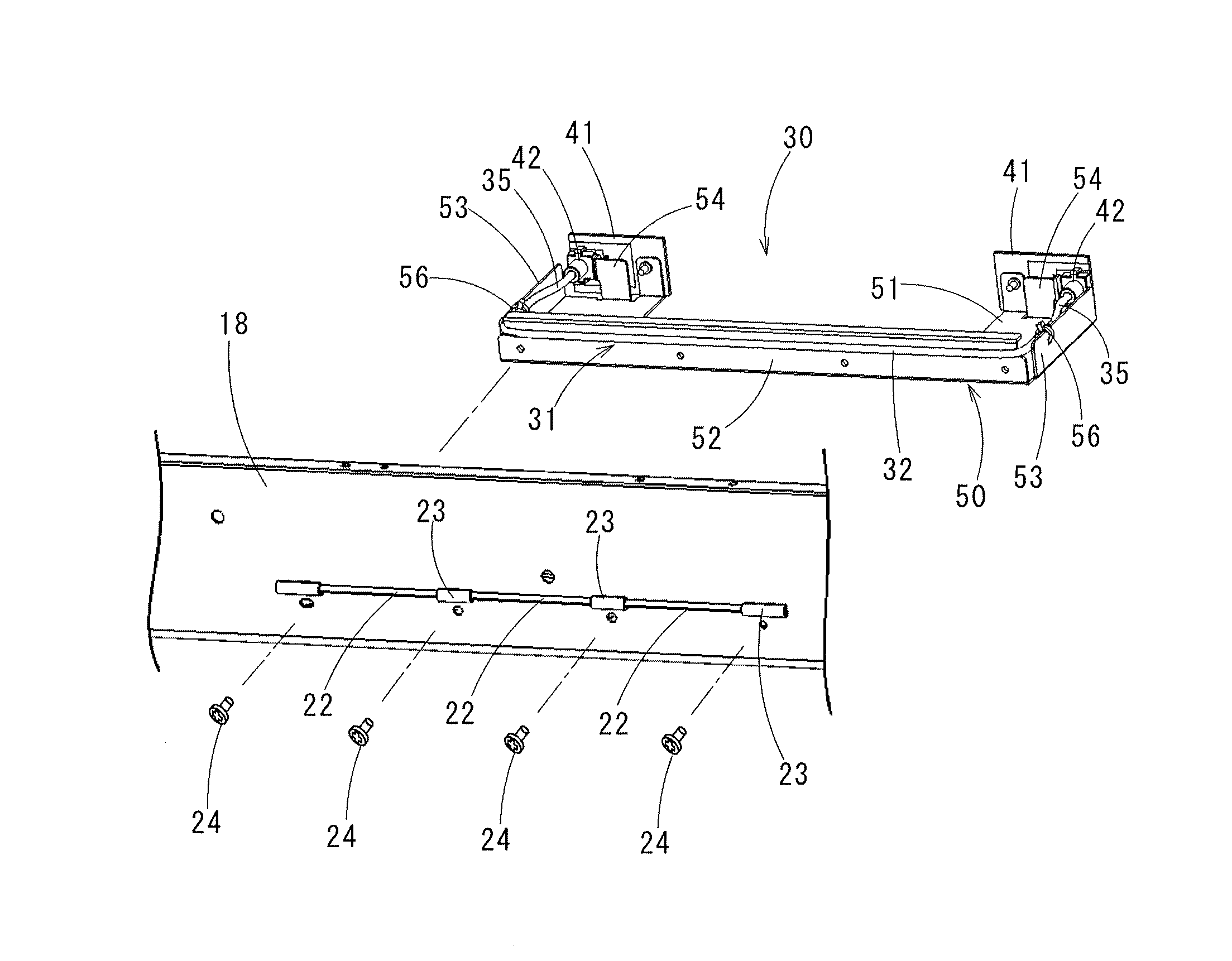
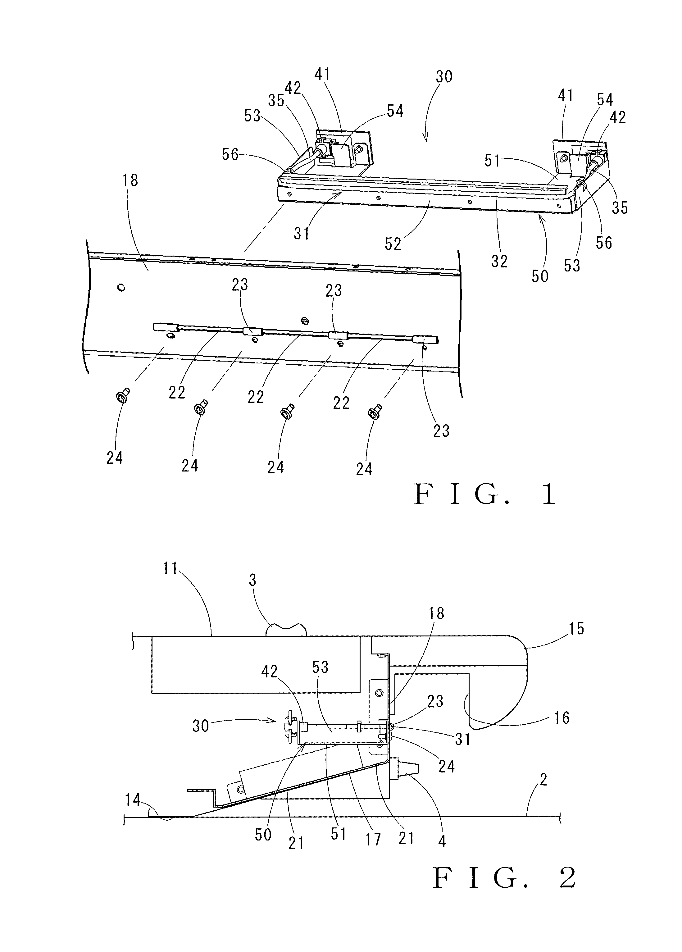
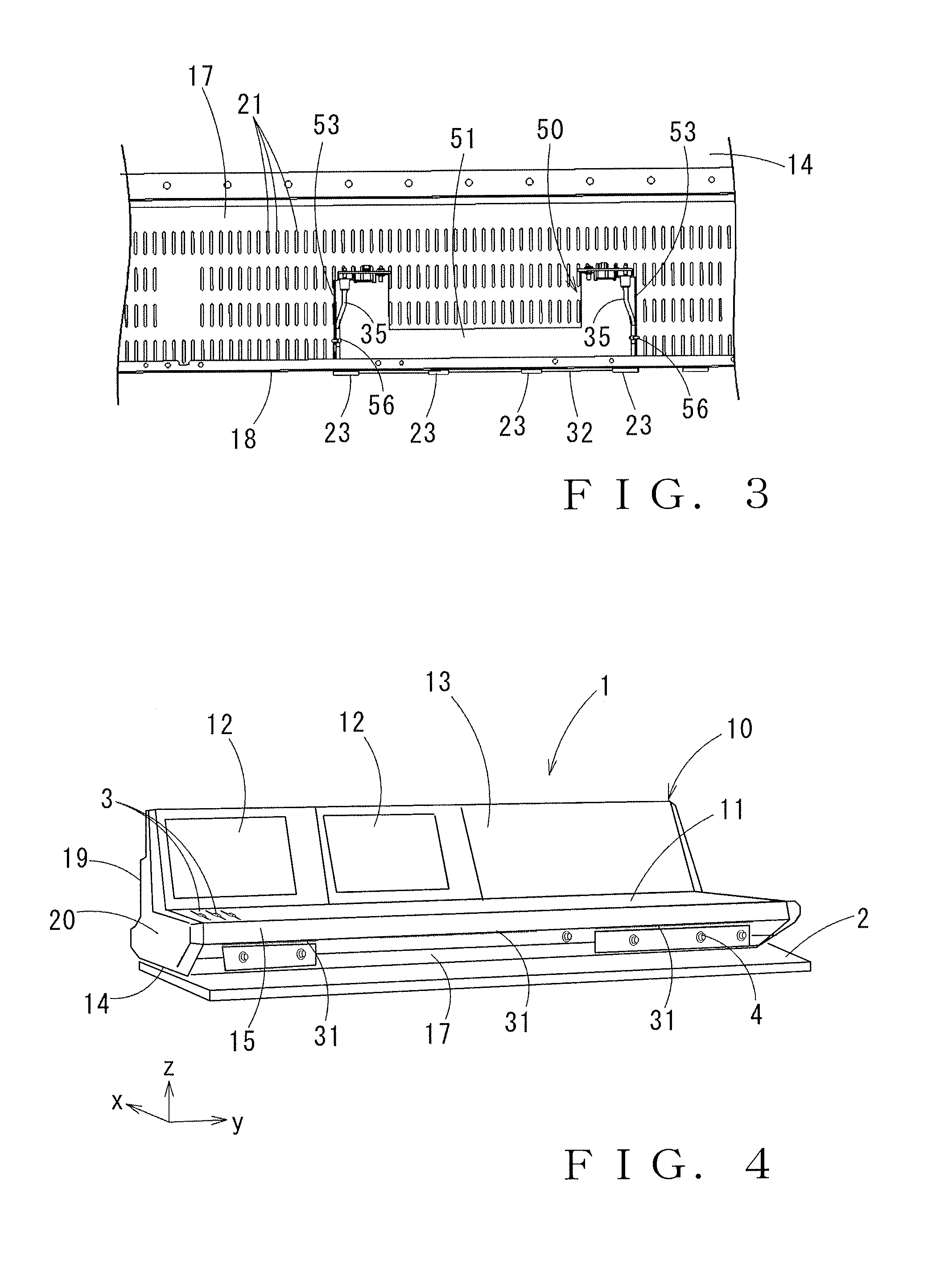
[0027]An audio equipment 1 is, as an overall appearance thereof being shown in FIG. 4, a mixer device used for mixing of audio signals, and the audio equipment 1 is used in a state where it is mounted on a table surface 2 or the like. The audio equipment 1 has formed thereon, at an upper surface portion of a housing 10 thereof, a flat panel portion 11 provided with a plurality of columns of channel strips having a plurality of fader controller knobs 3 that adjust parameter values for audio signal processing in input channels, and a slanted panel portion 13 on which displays 12 and controller knobs or the like, not shown, are arranged side by side. A human operator is situated on a front side (right-hand side toward the front in FIG. 4) of the flat panel portion 11, and the slanted panel portion 13 is arranged toward a rear side of the flat panel portion 11. The human operator operates the respective controller knobs or the like of both of the panel portions 11, 13. Hereinafter, unle...


PUM


Abstract

A linear opening is formed in a front wall portion of a housing of an audio equipment, and a bracket retaining a linear light guide member is installed on a rear side of the front wall portion such that at least one side of the light guide member is exposed at the opening. Both ends of the light guide member extend in the bracket in a direction away from the opening, and an LED as a light source is connected to each end via a coupler. Accordingly, noise generated at the LED light source is less likely to leak outside from the housing of audio equipment.

Description

BACKGROUND[0001]The invention relates to an audio equipment having a linear lighting device on an outer surface of a housing and to a bracket for the linear lighting device of the audio equipment.[0002]It is known in the convention art that, in addition to lamps having round shapes or square shapes, lighting devices having linear shapes that are provided along a contour of a part of an outer face of a vehicle or the like. Such linear lighting devices not only serve their primary function as lighting devices but also enhance designability. For example, Japanese Patent Laid-open Publication No. 2007-203762 discloses a mounting device for a lighting device in which a light guide tube is attached around a peripheral edge of an automobile headlamp in a substantially circular shape. This light guide tube is formed as a soft and flexible round rod made of acrylic resin, and one end thereof is inserted in a tube case and connected to a light source within the tube case. Further, the entire ...

Claims


Application Information

Patent Timeline
Patent Type & Authority Applications(United States)
IPC IPC(8): F21V33/00F21V8/00
CPCF21V33/0056F21W2131/30F21Y2101/02G02B6/0008F21S8/00F21V17/10F21V21/108F21V33/0052F21Y2103/00F21Y2115/10G02B6/001
Inventor GOTOU, YASUYOSHI
Owner YAMAHA CORP
Why Eureka
Try Eureka