Push-button switch with good balance

Active Publication Date: 2019-11-07
DONGGUAN CITY KAIHUA ELECTRONICS
View PDF0 Cites 0 Cited by
  • Summary
  • Abstract
  • Description
  • Claims
  • Application Information

AI Technical Summary

Benefits of technology

[0004]In order to solve the above deficiencies, an object of embodiments of the present disclosure is to provide a push-button switch with good balance, which has

Problems solved by technology

The existing thin push-button switch using a metal piece as a moving contact piece lacks a touch feeling like a large push-button switch because of the limitation of the internal space in the switch.
Moreover, due to the unreasonable internal stru

Method used


Image

  • Push-button switch with good balance
  • Push-button switch with good balance
  • Push-button switch with good balance

Examples


embodiment 1

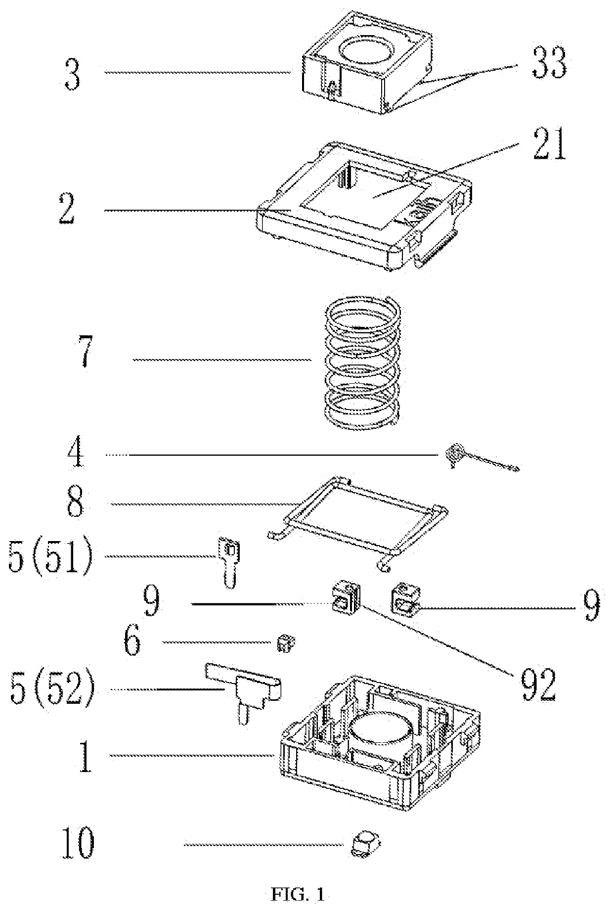
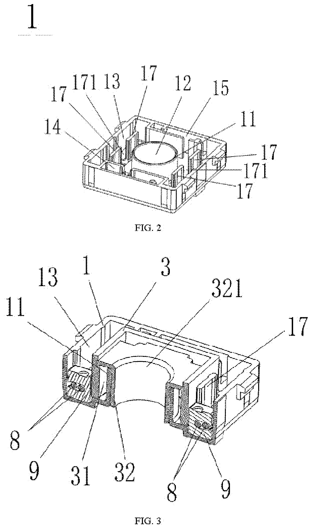
[0036]Referring to FIGS. 1-11, the present embodiment provides a push-button switch with good balance, including a base 1 and a cover 2 covering the base 1. The cover 2 is provided with an orifice 21. The push-button switch further includes a press core 3, a torsion spring 4, a conductive assembly 5 and a press core slider 6, which are respectively arranged on the base 1. A guide pillar 11 is protruded upwardly from a center position of an upper end of the base 1, and a guide hole 12 is arranged in a center of the guide pillar 11. One end of the base 1 is provided with a conductive assembly slot 14 configured to accommodate the conductive assembly 5, the other end of the base 1 is provided with a torsion spring slot 15 configured to accommodate the torsion spring 4. Two baffles 17 are arranged on the upper end of the base 1 and at each of opposite sides of the guide pillar 11. A gap is provided between the two baffles 17, such that an annular receiving slot 13 is formed around the b...

embodiment 2

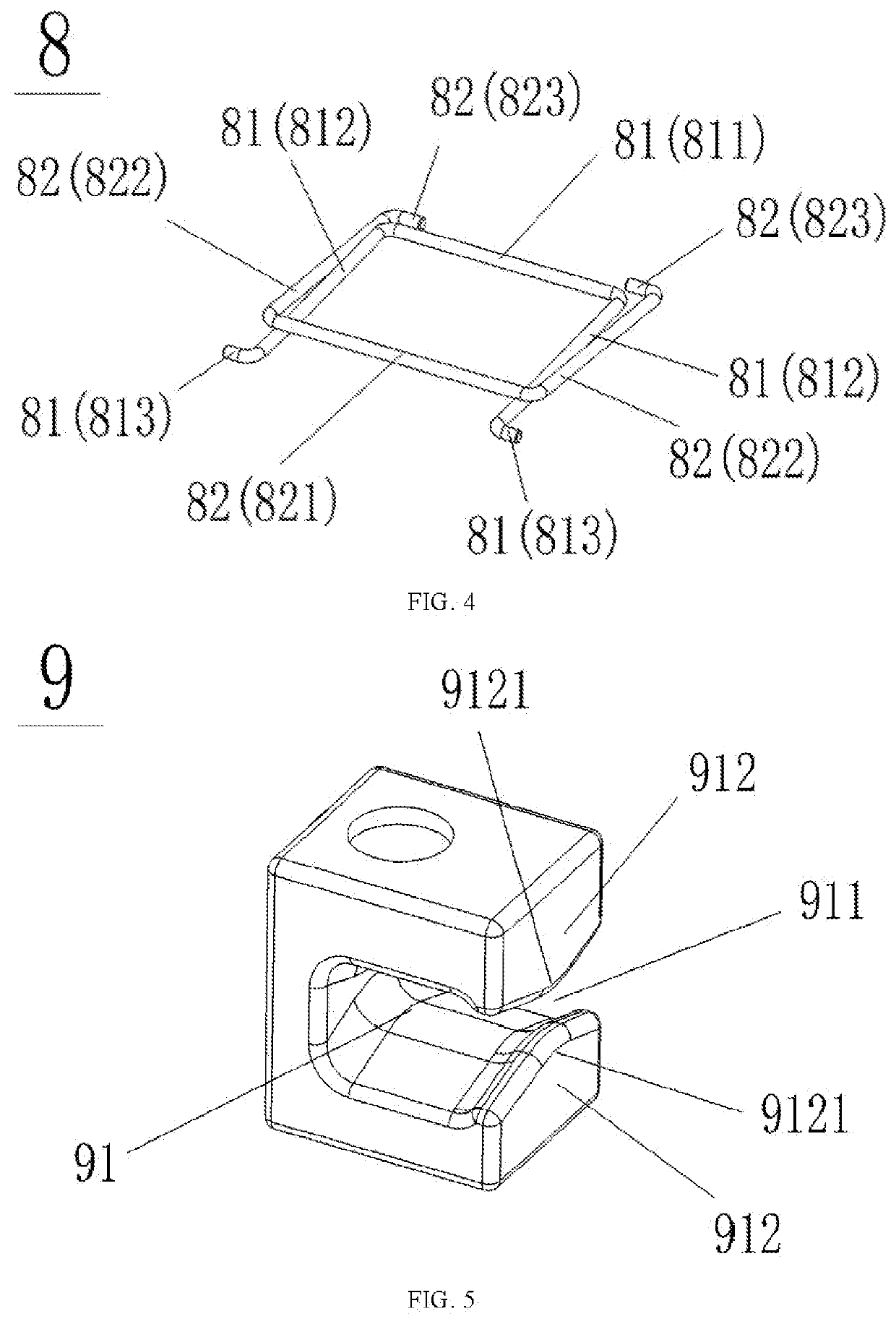
[0042]As shown in FIG. 12, a side edge of the positioning slider 9′ of the present embodiment is also provided with an arc limiting slot 91′ for clamping the first balance rod 81 and the second balance rod 82. The limiting slot 91′ has an opening 911′, and the upper portion and the lower portion of the opening 911′ are respectively bent inwardly to form protrusions 912′. However, the main difference between the present embodiment and the embodiment 1 is that the end faces of the protrusions 912′ in the present embodiment have no angle. The thickness of the positioning slider 9′ of the present embodiment is thinner than that of the positioning slider 9 of the embodiment 1.

embodiment 3

[0043]As shown in FIGS. 7, 10, 13-15, the main difference between the present embodiment and the embodiment 1 is, that a groove is formed in a lower end surface of the press core 3, such that a plurality of convex corners 33 are formed in the lower end surface of the press core 3. Meanwhile, a relief space is provided for the convex corners 33 by two manners. In one manner, a plurality of relief slots 16 for being inserted by the convex corners 33 are provided on the base 1 and outside of the guide pillar 11. In the other manner, a plurality of relief holes 16′ for being passed through by the convex corners 33 are provided on the base 1 and outside of the guide pillar 11.

[0044]In the present embodiment, the relief slots 16 and the relief holes 16′ have the same number as that of the convex corners 33. In the present embodiment, the number of the convex corners 33 is four, while the convex corners 33 may also be set to two or more according to specific needs.

[0045]Moreover, the heigh...


PUM


Abstract

A push-button switch with good balance, including a base, a cover covering the base, a press core, a torsion spring, a conductive assembly and a press core slider, which are respectively arranged on the base. A guide pillar provided with guide hole is protruded upwardly from a center of the base. Two baffles are arranged on the base and at opposite sides of the guide pillar to form an annular receiving slot provided with a balance rod assembly formed by a first and a second balance rod cross-connected with each other, two crossing junctions of which are limited by a positioning slider. A cylinder is protruded downward from a center of an annular slot formed at a lower end of the press core. The cylinder and the guide pillar are respectively inserted into the guide hole and the annular slot. The guide pillar is sleeved with a spring.

Description

CROSS-REFERENCE TO RELATED APPLICATIONS[0001]This application is a continuation of International Patent Application No. PCT / CN2017 / 117911, filed on Dec. 22, 2017, which claims the benefit of priority from Chinese Application No. 201611219898.7, filed on Dec. 26, 2016. The entirety of each of the above-mentioned patent applications is hereby incorporated by reference herein and made a part of this specification.TECHNICAL FIELD[0002]The present disclosure relates to a push-button switch, and more particularly to a push-button switch with good balance.BACKGROUND OF THE INVENTION[0003]Push-button switch is generally used as an input means for operating an electronic equipment. The quality of the push-button switch determines the experience of an relating input device, which requires the push-button switch to be made with a good touch feeling and acoustic feeling. The existing thin push-button switch using a metal piece as a moving contact piece lacks a touch feeling like a large push-bu...

Claims


Application Information

Patent Timeline
IPC IPC(8): H01H13/14H01H13/10H01H13/02H01H13/52
CPCH01H13/52H01H13/023H01H13/10H01H13/14H01H3/125H01H2013/525
Inventor WU, FUXI
Owner DONGGUAN CITY KAIHUA ELECTRONICS
Why Eureka
Try Eureka