
Electronic device and projection apparatus

a technology of electronic devices and projection devices, which is applied in the direction of picture reproducers, electric apparatus casings/cabinets/drawers, instruments, etc., can solve the problems of insufficient cooling of electronic devices, increased temperature of cooling air, and possible insufficient cooling of control panels

Active Publication Date: 2020-01-30
SEIKO EPSON CORP
View PDF0 Cites 6 Cited by
  • Summary
  • Abstract
  • Description
  • Claims
  • Application Information

AI Technical Summary

Benefits of technology

This patent describes two types of electronic devices: a projection apparatus and an electronic device main body. Both devices are accommodated in an accommodation apparatus. The accommodation apparatus includes a first enclosure that has a first intake port and a first discharge port, as well as a partitioner that separates the enclosure into two spaces. The electronic device main body is placed in the first space, while the light source and projection optical apparatus are placed in the second space. The projection apparatus also has a second intake port and a second discharge port. The patent also describes the use of a shutter and filter in the accommodation apparatus. The patent aims to improve the cooling and air flow within the electronic devices, which can affect their performance and reliability.

Problems solved by technology

The ventilator described in JP-A-2013-62425, however, has a problem of possible insufficient cooling of the control panel (electronic device).
The temperature of the cooling air therefore increases, and the electronic device is not sufficiently cooled when operating in a hot environment, such as in summer.

Method used


Image

  • Electronic device and projection apparatus
  • Electronic device and projection apparatus
  • Electronic device and projection apparatus

Examples


embodiment

[0026]The present embodiment will be described with reference to a projection apparatus which serves as an electronic device and in which a projector as an electronic device body is accommodated in an accommodation apparatus. The projection apparatus can be preferably used, for example, in projection mapping or other applications with the projection apparatus installed outdoors all the time.

Projection Apparatus

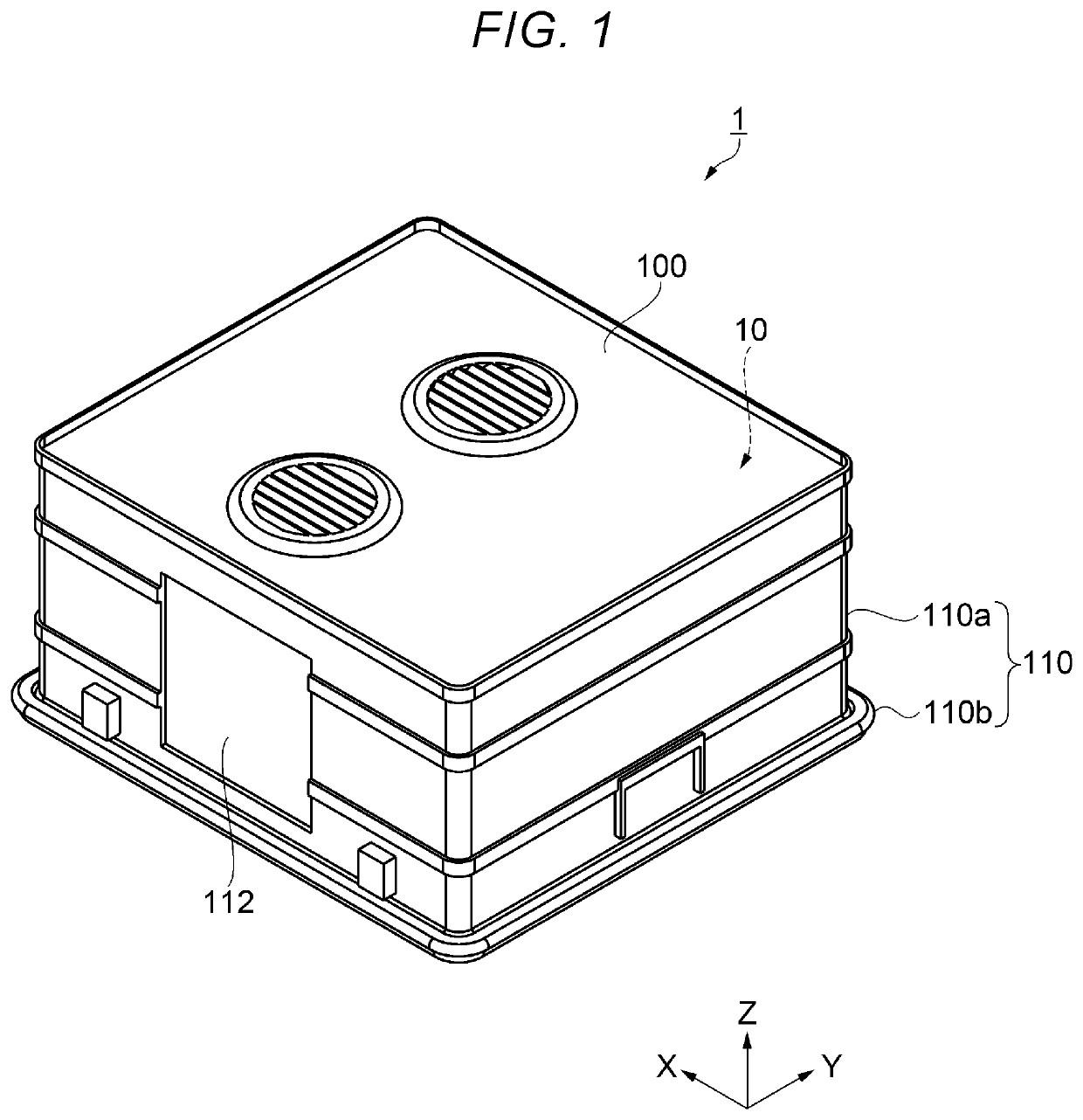
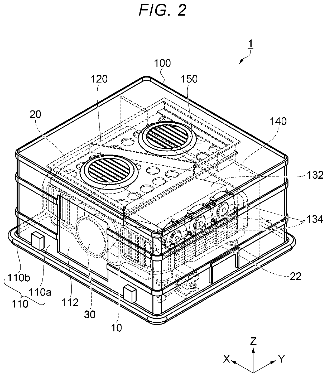
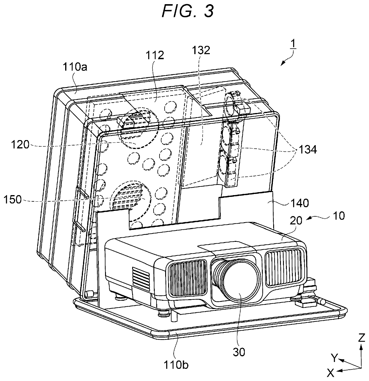
[0027]The configuration of the projection apparatus according to the present embodiment will be described with reference to FIGS. 1, 2, and 3. FIG. 1 is a perspective view showing the exterior appearance of the projection apparatus according to the embodiment. FIG. 2 is a perspective view showing the configuration of the projection apparatus. FIG. 3 is a perspective view showing the configuration of the interior of the projection apparatus with an upper enclosure open. In FIG. 2, members in the projection apparatus are drawn with broken lines.

[0028]A projection apparatus 1 as ...


PUM


Abstract

An electronic device includes an electronic device main body and an accommodation apparatus accommodating the electronic device main body. The accommodation apparatus includes a first enclosure forming an internal space and having a first intake port and a first discharge port, a partitioner partitioning the internal space into a first space and a second space, and a first intake fan sending the air into the first space. The electronic device main body includes a second enclosure having a second intake port and a second discharge port, and a second intake fan sucking air into the electronic device main body. The second intake port is disposed in the first space. The second discharge port is disposed in the second space. The amount of air sent by the first intake fan into the first space is greater than the amount of air sucked by the second intake fan into the second enclosure.

Description

[0001]The present application is based on, and claims priority from JP Application Serial Number 2018-139102, filed Jul. 25, 2018, the disclosure of which is hereby incorporated by reference herein in its entirety.BACKGROUND1. Technical Field[0002]The present disclosure relates to an electronic device and a projection apparatus.2. Related Art[0003]An electronic device installed outdoors has been known. For example, JP-A-2013-62425 proposes a ventilator that prevents entry of rainwater and corresponds to an electronic device installed outdoors. The ventilator is provided with an opening and a fan that cause air to flow through an enclosure of a control panel as the electronic device for ventilation (cooling).[0004]JP-A-2013-62425 is an example of the related art.[0005]The ventilator described in JP-A-2013-62425, however, has a problem of possible insufficient cooling of the control panel (electronic device). In detail, when the ventilation is performed, the air having cooled the inte...

Claims


Application Information

Patent Timeline
Patent Type & Authority Applications(United States)
IPC IPC(8): G03B21/16G03B21/14H05K7/20H04N9/31
CPCH05K7/20181H05K7/20145H04N9/3141G03B21/145G03B21/16H05K7/20136H05K5/0213H04N9/3144G03B21/54
Inventor IINUMA, KAZUYUKI
Owner SEIKO EPSON CORP
Learn More