Gearshift lever device

a technology of lever device and gear shift, which is applied in the direction of gearing control, mechanical equipment, transportation and packaging, etc., can solve the problem that the gear shift lever device has difficulty in forcibly releasing the shift lock

Inactive Publication Date: 2020-03-05
FUJI KIKO CO LTD
View PDF0 Cites 1 Cited by
  • Summary
  • Abstract
  • Description
  • Claims
  • Application Information

AI Technical Summary

Benefits of technology

[0007]According to a gearshift lever device of an aspect of the present invention, it is possible to enable forcible release o

Problems solved by technology

However, there is a case where the shift-lock is forcibly released by manually pushing a release rod instead of activating the actuator.
In this case, some configuratio

Method used


Image

  • Gearshift lever device
  • Gearshift lever device
  • Gearshift lever device

Examples


Embodiment Construction

[0021]An embodiment of the present invention is described below in detail with reference to the drawings.

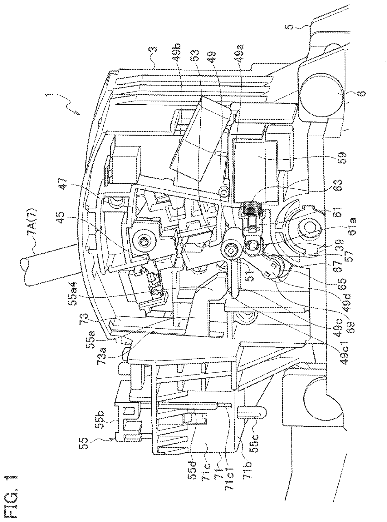
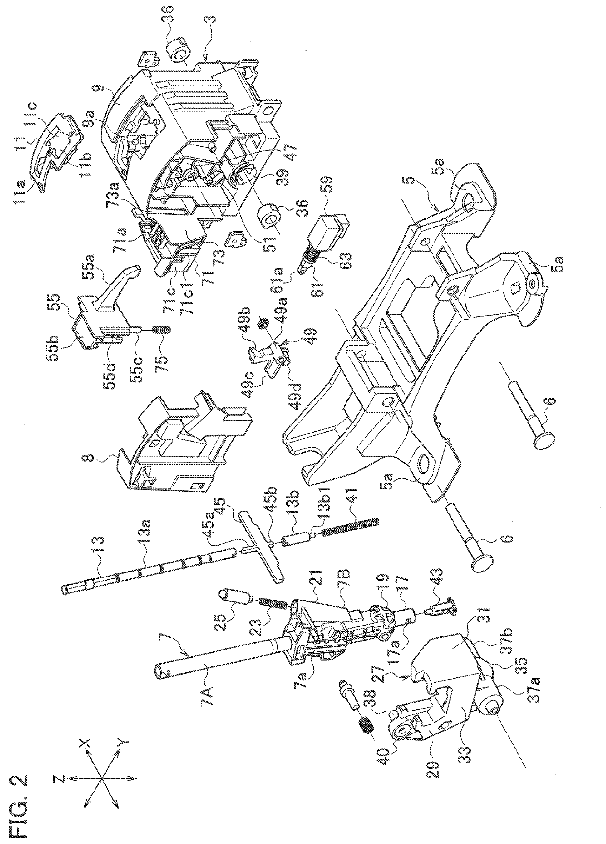
[0022]FIG. 1 illustrates an internal configuration of a gearshift lever device 1 used in a vehicle (an automobile). In the following descriptions, “front-rear direction” and “right-left direction” respectively correspond to a front-rear direction and a right-left direction of the vehicle in which the gearshift lever device 1 is mounted. In FIG. 2, an arrow X indicates the right-left direction (select direction), an arrow Y indicates the front-rear direction (shift direction), and an arrow Z indicates a top-down direction (vehicle top-down direction). In the gearshift lever device 1, a housing 3 is assembled on a base 5 illustrated in FIG. 2 with fix pins 6. The base 5 is fixed on an unillustrated vehicle body using mounting portions 5a. A lower portion of a gearshift lever 7 is inserted to the housing 3. A cover 8 is put on one opening in the right-left direction X of the housing...


PUM


Abstract

A gearshift lever device of this invention includes: a shift-lock lever that restricts a downward movement of a position pin when the gearshift lever is in a parking position; and a forcible release lever that presses a second arm and thereby forcibly rotates the shift-lock lever to allow the position pin to move downward. The forcible release lever includes a pressing portion that presses the second arm. The pressing portion includes a first corner portion that presses a position away from the rotational center of the shift-lock lever and a second corner portion that presses a position closer to the rotational center of the shift-lock lever than the position pressed by the first corner portion. When the pressing portion presses the second arm, the first corner portion first comes into contact with the second arm first and thereafter the second corner portion comes into contact with the second arm.

Description

CROSS REFERENCE TO RELATED APPLICATION[0001]The present application is based on, and claims priority from Japanese Patent Application No. 2018-162606, filed Aug. 31, 2018, the disclosure of which is hereby incorporated by reference herein in its entirety.TECHNICAL FIELD[0002]The present invention relates to a gearshift lever device including a shift-lock mechanism.BACKGROUND ART[0003]There has been known a gearshift lever device that includes a shift-lock mechanism that disables operations of a gearshift lever by prohibiting an operation of an operation button on the gearshift lever while the gearshift lever is in a parking position (see Japanese Patent Application Publication No. H11-301295). In a state where shift-lock is released, a compression rod is moved downward with a position pin in the gearshift lever by operating the operation button. In a state where the shift-lock is working, the position pin is in contact with a shift-lock lever and restricts the downward movement of t...

Claims


Application Information

Patent Timeline
IPC IPC(8): F16H59/10F16H51/00
CPCF16H51/00F16H2059/026F16H2059/0282F16H59/10B60K20/02F16H59/0204F16H59/105F16H61/22F16H2061/223
Inventor MATSUMOTO, AKIOTAKIKAWA, YOSHIHIROKUBOTA, KATSUSHIHAKAMATA, TAKUMI
Owner FUJI KIKO CO LTD
Why Eureka
Try Eureka