Clickable knob for touch sensors

a touch sensor and clickable technology, applied in the field of clickable knobs, can solve the problems of not being able to haptically feel and/or hear the click, the click is sometimes not correctly detected, and the clickable knobs of the state of the art are quite large, so as to improve the user feedback and increase the detection quality of the click

Active Publication Date: 2020-03-05
ADVANCED SILICON
View PDF0 Cites 9 Cited by
  • Summary
  • Abstract
  • Description
  • Claims
  • Application Information

AI Technical Summary

Benefits of technology

[0007]It is the object of the present invention to find a clickable knob for a touch se

Problems solved by technology

This mechanism has however the disadvantage that movable click detection point is sometimes not brought close enough to the touch sensor surface such that the click is sometimes not correctly detected.
However, this has the disadvantage that the user is not able to haptically feel and/or to hear the click due to the missing click mechanism.
However, this has similar detection problems as the mechanical click mechanism described above, because the ke

Method used


Image

  • Clickable knob for touch sensors
  • Clickable knob for touch sensors
  • Clickable knob for touch sensors

Examples


Embodiment Construction

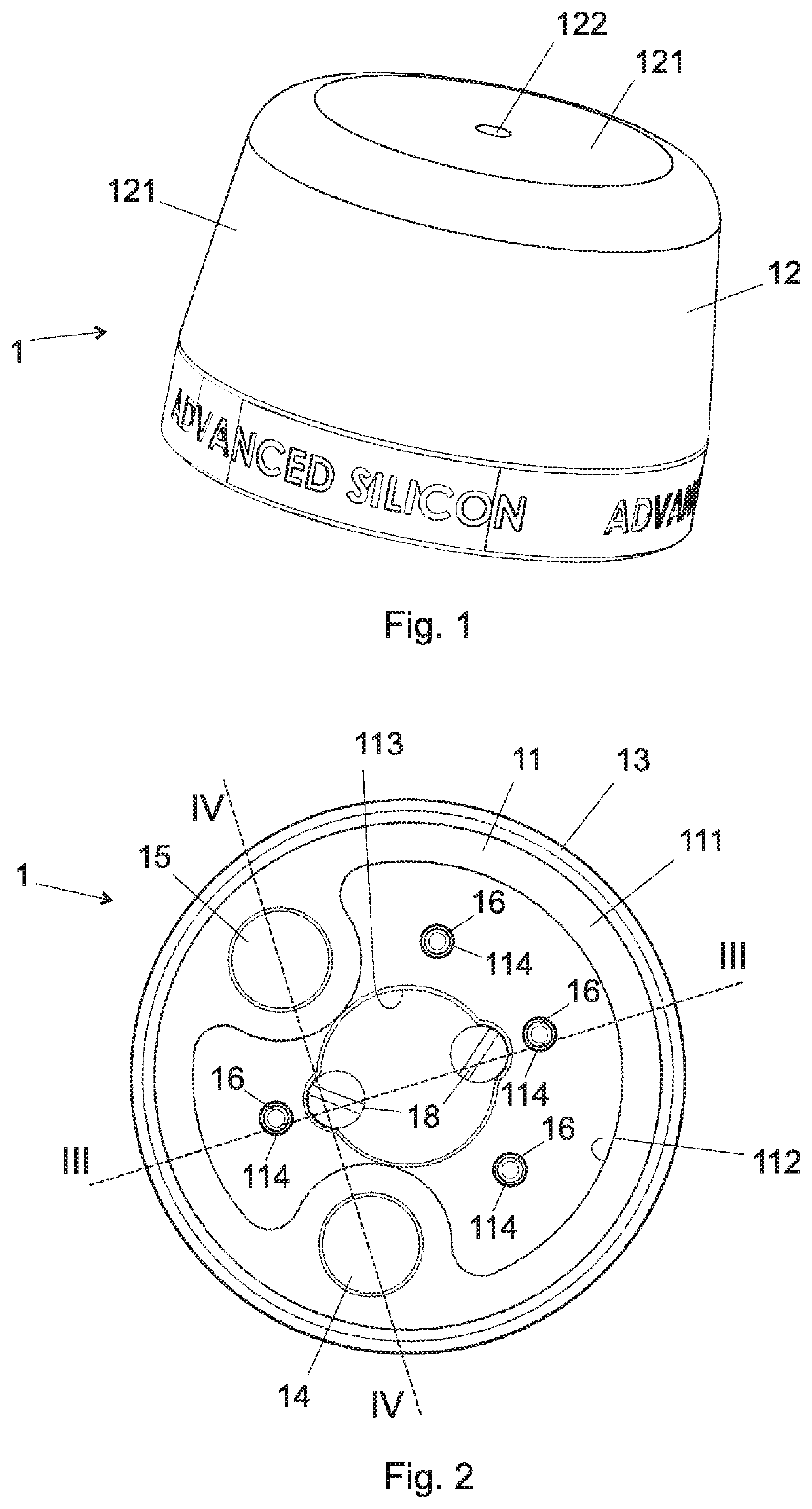
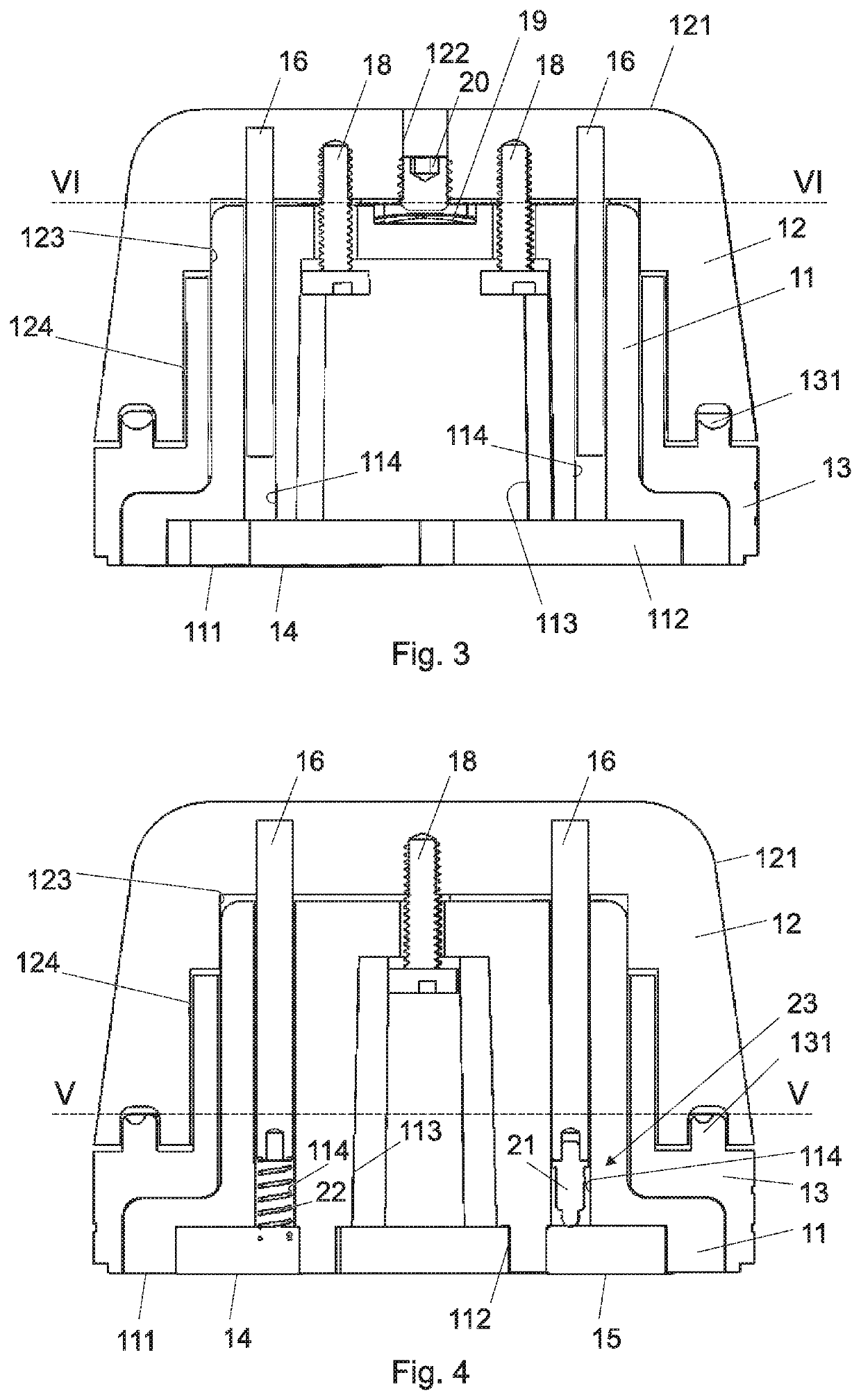
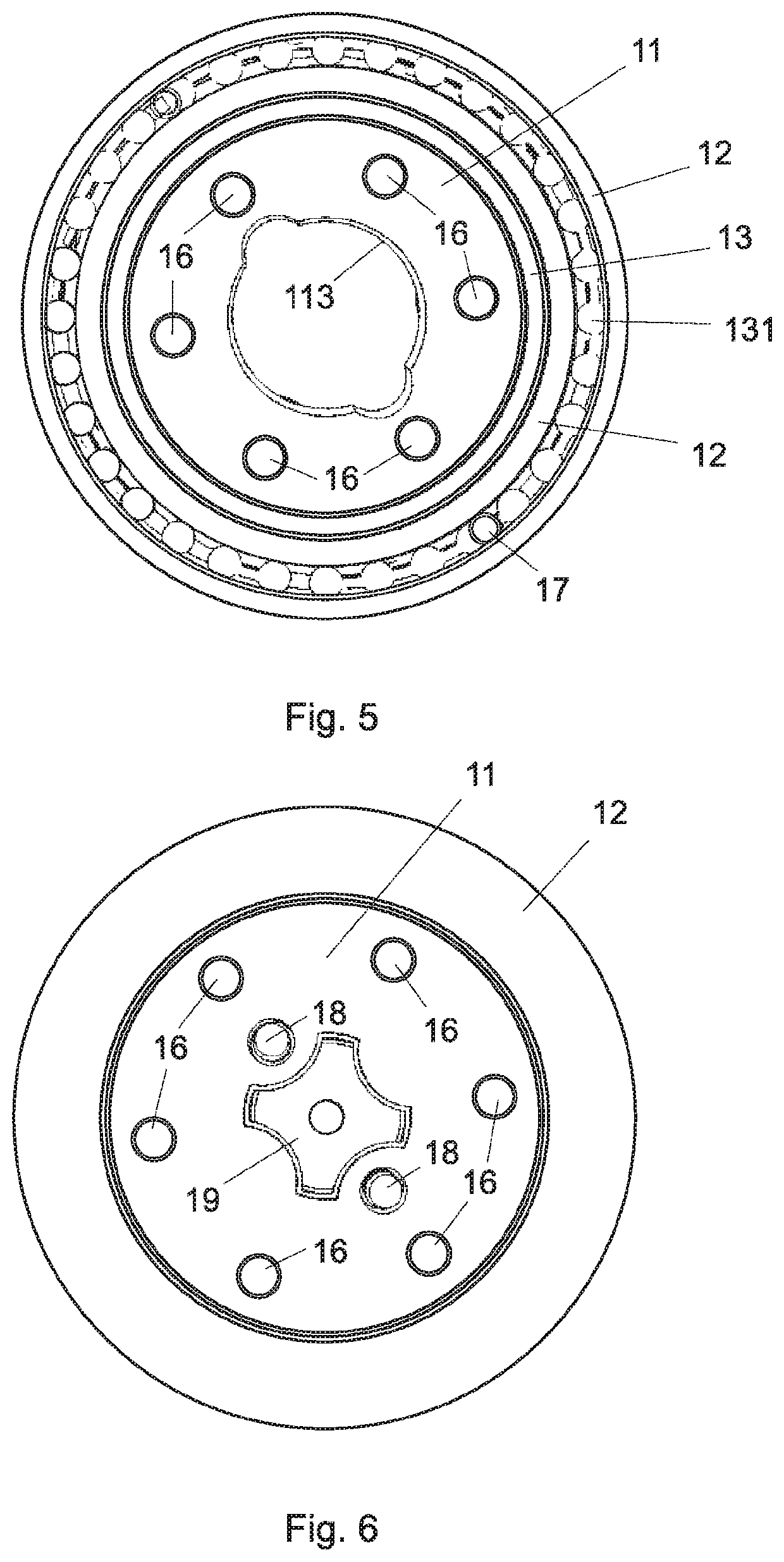
[0019]FIGS. 1 to 7 show a first embodiment of a clickable knob according to the invention for a touch sensor. A knob is a user input device which can be rotated around knob rotation axis in order to input a rotational state of the clickable knob. In addition, the clickable knob can be mechanically activated to perform a click input. A click input is a selection or confirmation input by a user similar to a mouse click. Thus, the clickable knob 1 has a click state. The click state comprises an unclicked state and a clicked state. The clickable knob 1 is normally in an unclicked state and can be pressed by the user in a clicked state. A clickable knob for a touch sensor means that, when the clickable knob can be placed on a touch sensor surface of a touch sensor / screen, the rotational state and the click state can be detected by the touch sensor (without the necessity of an electric connection to the user input device). The clickable knob 1 in the FIGS. 1 to 7 is shown in the clicked s...


PUM


Abstract

Clickable knob configured to be placed on a touch sensor surface of a touch sensor and to allow the touch sensor to detect a rotational state of the clickable knob and a click state, wherein the click state comprises a clicked state and an unclicked state, the knob (1) comprising:
  • a first knob element (11) comprising a bottom surface (111) configured to face the touch sensor surface, when placed on the touch sensor surface for the detection of the rotational state and the click state, wherein the bottom surface (111) of the first knob element (11) comprises a rotation detection point (14) allowing the detection of the rotational state of the knob (1) in the touch sensor and a click detection point (15) allowing the detection of the click state of the knob (1) in the touch sensor;
  • a second knob element (12) supported such that a rotation of the second knob element (12) causes a corresponding rotation of the first knob element (11) and that the second knob element (12) can be moved in a click direction relative to the first knob element (11) between the unclicked state and the clicked state, wherein the
  • second knob element (12) in the clicked state is moved closer to the first knob element (11) than in the unclicked state, wherein the second knob element (12) comprises a user surface (121) which is configured to be touched by a user for rotating and/or clicking the knob (1), wherein the user surface (121) is conductively connected to the rotation detection point (14); and
  • a spring means (19) arranged such between the first knob element (11) and the second knob element (12) that the knob (1) is maintained in the unclicked state and such that a force of the spring means (19) acts against a force of the user, when the user moves the second knob element (12) towards the first knob element (11);
  • wherein the user surface (121) is conductively connected to the click detection point (15) over a switch means (23, 19), wherein the switch means (23, 19) conductively connects the user surface (121) with the click detection point (15), when the knob (1) is in the clicked state and/or when the second knob element (12) is moved towards the first knob element (11), and conductively separates the user surface (121) from the click detection point (15), when the knob (1) is in the unclicked state.

Description

REFERENCE DATA[0001]The present application claims the priority of European Patent Application EP20180191863, filed on Aug. 30, 2018, the content of which is incorporated here by reference.FIELD OF THE INVENTION[0002]The present invention concerns a clickable knob which can be placed on a touch sensor for providing a physical clickable knob on the touch sensor. The detection of the user input of the clickable knob, i.e. the click state and the rotation state, is detected based on a the detection of corresponding click and rotation detection points of the clickable knob by touch pixels of the touch sensor.DESCRIPTION OF RELATED ART[0003]In the state of the art, the knob comprises a click mechanism which moves the click detection point closer to the touch sensor surface, when the click mechanism is activated. This mechanism has however the disadvantage that movable click detection point is sometimes not brought close enough to the touch sensor surface such that the click is sometimes ...

Claims


Application Information

Patent Timeline
IPC IPC(8): G06F3/0362G06F3/0488H01H25/06
CPCH01H25/065G06F3/0362G06F3/0488G06F3/039G06F3/0393G06F3/044G06F3/016G06F3/0446G06F2203/04112
Inventor BALLAN, HUSSEINMARÉCHAL, SYLVAINPASTRE, MARC
Owner ADVANCED SILICON
Why Eureka
Try Eureka