
Emergency assistance method and device for a firearm

Active Publication Date: 2020-03-12
SOLID PROOF TECH
View PDF2 Cites 2 Cited by
  • Summary
  • Abstract
  • Description
  • Claims
  • Application Information

AI Technical Summary

Benefits of technology

The present invention provides an emergency assistance device for a firearm that allows users to communicate with emergency services and record audio and video of a personal defense situation. The device is easy-to-use, inexpensive, and retrofittable, and it does not restrict the user's field of view. It can be quickly affused to the firearm without having to take it to a gunsmith and can be disposed on the bottom of the firearm's magazine or trigger guard. The device reduces accidental communication with emergency services by featuring a recessed button or a protrusion around the button.

Problems solved by technology

For example, in a home invasion scenario, events may unfold rapidly, and emergency services may not be able to respond before the threat materializes.
These actions necessarily require the person to remove at least one hand from the firearm, which reduces the person's grip on the firearm and negatively impacts the accuracy and precision of the firearm.
However, in order to utilize the radio communications in these devices, a firearm user would have to buy a firearm with a communication system already integrated into the firearm or hire a gunsmith to integrate a communication system into the firearm.
The use of deadly force is a serious event.
However, recording audio from the waist of a person is not optimized to record the audio of a conversation between a home owner and an intruder because the microphone is not positioned between the home owner and the intruder, and an item such as clothing may cover the microphone and obstruct any audio recording.
A device that is mounted on top of a firearm necessarily obstructs the user's field of view.
Even when the device is mounted to the side of the firearm's sight, a user's field of view is still limited and there is an increased likelihood that a user will miss cues from the environment, including threats to the user's health.
The device in the '248 publication is limited to peer-tip-peer network due to security issues, and thus a user may not transmit an emergency call or audio / visual data across a cell phone network.

Method used


Image

  • Emergency assistance method and device for a firearm
  • Emergency assistance method and device for a firearm
  • Emergency assistance method and device for a firearm

Examples


Embodiment Construction

[0074]As described in detail below, various embodiments of the present invention include an emergency assistance device. The present invention has significant benefits across a broad spectrum of endeavors. It is the Applicant's intent that this specification and the claims appended hereto be accorded a breadth in keeping with the scope and spirit of the invention being disclosed despite what might appear to be limiting language imposed by the requirements of referring to the specific examples disclosed.

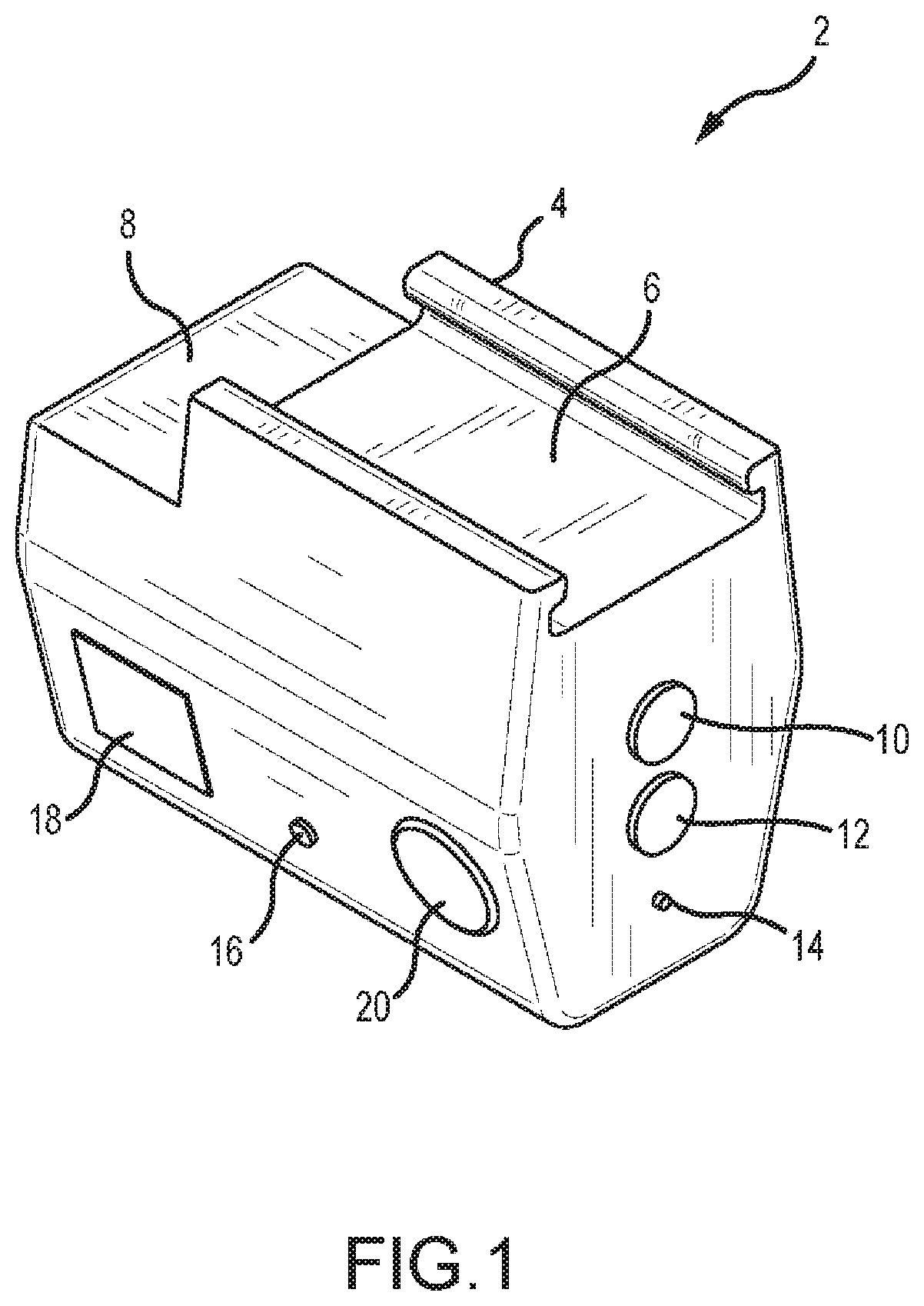
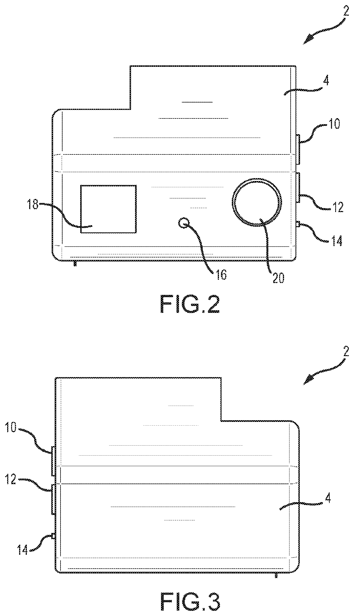
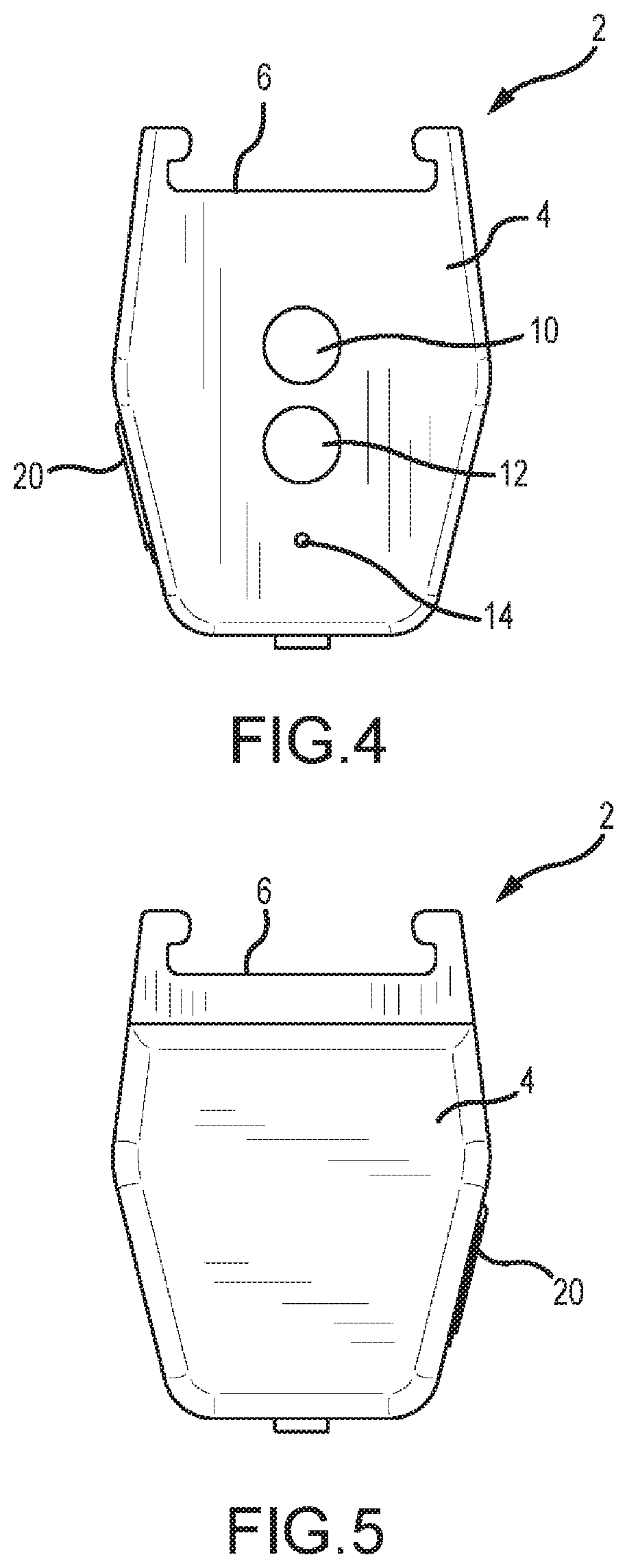
[0075]FIGS. 1-7 depict various views of an emergency assistance device 2 that can be selectively mounted to a firearm. FIG. 1 is a perspective view of the emergency assistance device 2 with various features. First, the emergency assistance device 2 has a housing 4 that provides a location for many of the features to be disposed and also protects the more sensitive components of the device 2. In some embodiments, the housing 4 is made from injection molded plastic such as polyethylene ...


PUM


Abstract

The present invention generally relates to an attachment for a firearm that communicates with remote device or person such as emergency services. One embodiment of the present invention is selectively interconnected to a picatinny rail, weaver rail, or other mounting means, and the embodiment includes a button that allows a user to initiate communication with emergency services without removing his or her hands from the firearm.

Description

CROSS-REFERENCE TO RELATED APPLICATIONS[0001]This application is a continuation-in-part of U.S. patent application Ser. No. 15 / 426,179, filed Feb. 7, 2017, which is a continuation of U.S. patent application Ser. No. 14 / 804,049, filed Jul. 20, 2015, which claims priority under 35 U.S.C. § 119(e) to U.S. Provisional Patent Application Ser. No. 62 / 026,344 filed Jul. 18, 2014, which is incorporated herein in its entirety by reference.FIELD OF INVENTION[0002]This invention generally relates to firearms. More specifically, the present invention relates to an emergency assistance method and device for firearms.BACKGROUND OF THE INVENTION[0003]Firearms are popular in the United States and firearm purchases have increased significantly in recent years. The Federal Bureau of Investigation reports that 19,592,303 total background checks were processed by the National Instant Criminal Background Check System (“NICS”) in 2012, compared to 11,177,335 checks in 2007. People purchase firearms for a...

Claims


Application Information

Patent Timeline
IPC IPC(8): H04N5/77G01S19/17F41G1/35G11B27/34H04N5/232G01S19/13F41A17/06
CPCG01S19/13H04N5/232G11B27/34F41G1/35G01S19/17F41A17/063H04N5/772H04N5/77H04N7/181G01S3/8036H04N23/60
Inventor SAKIEWICZ, PAULBEYE, II, WILLIAM DEANTUERTSCHER, ALBERT
Owner SOLID PROOF TECH
Learn More