Underground mining system for reduced costs, improved efficiencies, higher productivity and a safer working environment through penetrated block extraction

a mining system and mining technology, applied in surface mining, directional drilling, gas removal, etc., can solve the problems of increasing operating costs and removing more material per volume, and achieve the effect of reducing mining costs and reducing separation

Active Publication Date: 2018-10-30
UNDERGROUND EXTRACTION TECH
View PDF21 Cites 1 Cited by
  • Summary
  • Abstract
  • Description
  • Claims
  • Application Information

AI Technical Summary

Benefits of technology

[0011]Advantageously, narrow elongate pillars may be left between adjacent plunge cuts, thereby resulting in greater material removal per volume and improved operating costs when compared with bord and pillar mining.
[0019]Advantageously, the continuous miner and flexible conveyor system represent significantly lower initial capital and equipment costs than long wall mining. Further, the continuous miner is more adaptable in following an interrupted coal seam along or through a fault line or other discontinuity.
[0022]The system may include an operating centre (ROC) for remotely operating the continuous miner. As no mining personnel are present in the plunge cuts, the roof of each plunge cut need not be reinforced resulting in reduced costs and time, and substantially improved safety outcomes. The ROC may wirelessly communicate with the continuous miner over the Ethernet.
[0028]The continuous miner coupled to a flexible conveyor system may be unmanned. Accordingly, the roof of each plunge cut need never be reinforced. The plunge cuts may be of a depth to receive the continuous miner and, at least in part, the flexible conveyor system. The plunge cuts may receive most of the flexible conveyor system. The plunge cuts may be: greater than 100 m in length, greater than 200 m in length, greater than 300 m in length, greater than 400 m in length, or greater than 500 m in length. The plunge cuts may be between 30 m and 550 m deep. Accordingly, adjacent sets of gate roads could be up to 800 m or more apart, a substantially greater separation between gate roads than in long wall mining, which further reduces the mining costs.
[0029]The method may involve sealing each dead end plunge cut during its formation. The method may involve supplying inert gas (e.g. carbon dioxide or nitrogen) in each sealed plunge cut to avoid hazards such as frictional ignition, methane ignition as it is emitted from the coal or coal dust ignition in extreme events.

Problems solved by technology

Advantageously, narrow elongate pillars may be left between adjacent plunge cuts, thereby resulting in greater material removal per volume and improved operating costs when compared with bord and pillar mining.

Method used


Image

  • Underground mining system for reduced costs, improved efficiencies, higher productivity and a safer working environment through penetrated block extraction
  • Underground mining system for reduced costs, improved efficiencies, higher productivity and a safer working environment through penetrated block extraction
  • Underground mining system for reduced costs, improved efficiencies, higher productivity and a safer working environment through penetrated block extraction

Examples


Embodiment Construction

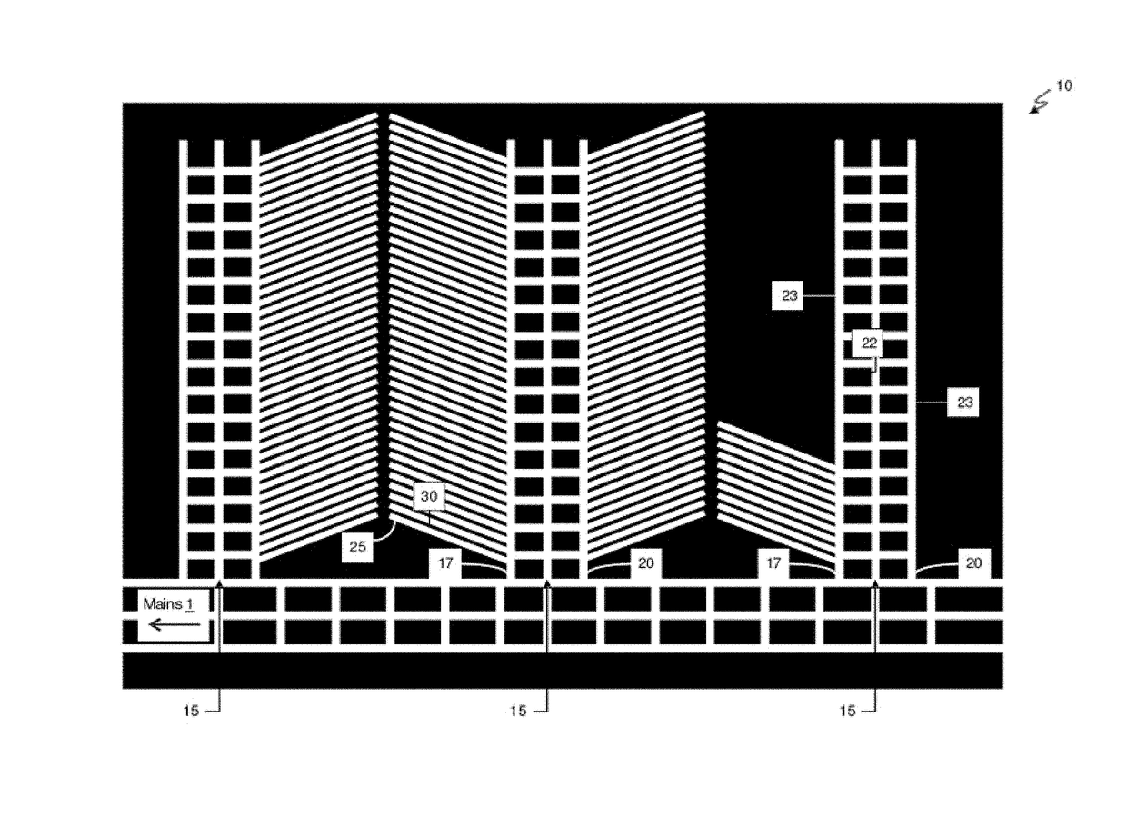
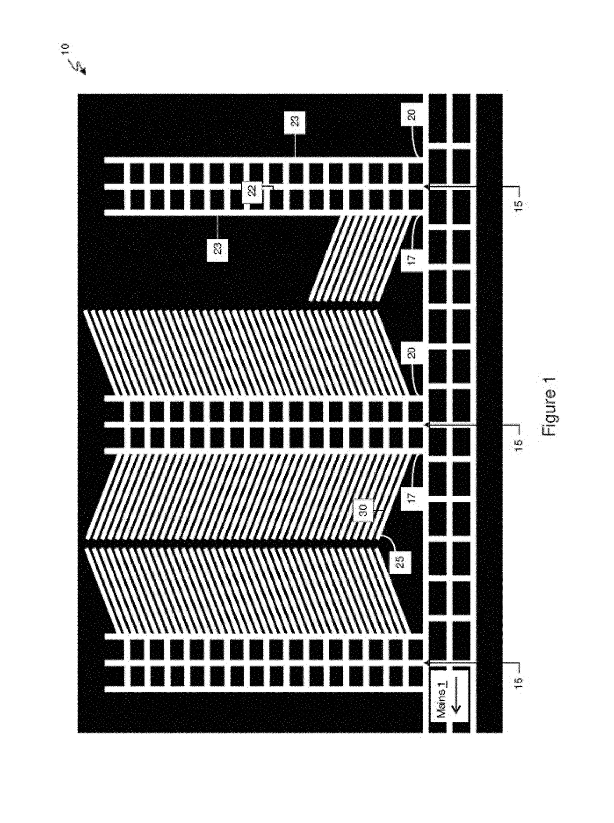
[0053]According to an embodiment of the present invention, there is provided an underground coal mine 10 as shown in FIG. 1. Tunnels are formed in a coal seam of the mine 10. Elaborating further, the mine 10 includes a triplet of main headings 1, and a triplet of spaced apart sets 15 of gate roads 17, 20 extending perpendicularly from the main headings 1 (also termed “main gates” or simply “mains”). Each set 15 of gate roads includes a triplet of gate roads or separated headings 17, 20. The mine 10 further includes cut-throughs extending between adjacent gate roads 17, 20 to form rectangular support pillars 22.

[0054]The mine 10 further includes two blocks of coal (i.e. valuable material) between adjacent sets 15 of gate roads 17, 20. Parallel dead-end plunge cuts 25 are formed in the coal blocks and extending obliquely from the sets 15 of gate roads 17, 20. Advantageously, narrow elongate coal pillars 30 are also left between adjacent plunge cuts 25, thereby resulting in greater mat...


PUM


Abstract

The present invention relates to a mining method including the step of forming one or more sets of gate roads. Each set of gate roads includes at least two headings typically for providing and retuning ventilation. Dead end plunge cuts extend from the sets of gate roads. Each plunge cut is formed with a continuous miner coupled to a flexible conveyor system. Each plunge cut is greater than 30 meters in length. Advantageously, narrow elongate pillars may be left between adjacent plunge cuts, thereby resulting in greater material removal per volume and improved operating costs when compared with bord and pillar mining.

Description

TECHNICAL FIELD[0001]The present invention generally relates to an underground mining system. The present invention has particular, although not exclusive application to coal and potash mining.BACKGROUND[0002]The reference to any prior art in this specification is not, and should not be taken as an acknowledgement or any form of suggestion that the prior art forms part of the common general knowledge.[0003]Coal mining is performed to extract coal, lying in seams, from the ground. Many techniques have been employed to extract coal seams over the years, varying from tunneling though to large open cut mines. Two contemporary underground coal mining techniques include long wall mining, and bord and pillar mining as described below.[0004]Long wall mining is a form of underground mining where a block of coal is mined using a moving long wall. A number of hydraulic jacks, called chocks, are placed in a long line in order to support the overlying strata (ie. the roof) at the coalface. The c...

Claims


Application Information

Patent Timeline
Patent Type & Authority Patents(United States)
IPC IPC(8): E21C41/18E21C41/16E21B7/04E21D15/00E21F7/00
CPCE21C41/18E21B7/046E21C41/16E21D15/00E21F7/00
Inventor MACDONALD, BRIANMAPP, MICHAEL
Owner UNDERGROUND EXTRACTION TECH
Why Eureka
Try Eureka