High performance fan tail heat exchanger

a heat exchanger and fan tail technology, applied in the direction of lighting and heating apparatus, laminated elements, semiconductor/solid-state device details, etc., can solve the problems of insufficient design of heat exchangers for dissipating heat generated by high-power electronic components, inability to adequately dissipate heat generated by these heat-generating components, and inability to meet the needs of high-power electronic components, etc., to achieve the effect of reducing pressure drop across the heat exchanger, reducing the volume volum

Inactive Publication Date: 2001-10-30
ADVANCED THERMAL SOLUTION
View PDF45 Cites 70 Cited by
  • Summary
  • Abstract
  • Description
  • Claims
  • Application Information

AI Technical Summary

Benefits of technology

It is even a further object of the invention to provide a novel heat exchanger design wherein the fins are in thermal communication with the base and affixed thereto such that the effective width of the wing span of the fins exceeds the width of the base. Commonly referred to as a fan tail, such an enlarged wing span, when compared to conventional heat exchangers, provides an increased control volume thereby allowing a greater volume of fluid flow to enter the fin field.
In yet a further embodiment of the invention, the novel heat exchanger comprises a fin density of at least ten fins per inch or greater of base length thereby providing a narrow channel heat exchanger with a fan tail. The aspect ratio of the individual channels between the fins, as compared to parallel fins affixed perpendicular to the base through an extrusion method, generates a reduced pressure drop across the heat exchanger. Accordingly, the fluid flow entering the heat exchanger is increased.
It is even a further object of the invention to provide a novel heat exchanger comprising fins with surface modifications and communication means. An increased surface area of the heat exchanger is among the benefits associated with surface modifications, such as undulations. In addition, the communication means provides for a more effective cooling of the heat generating component by the fluid passing through the heat exchanger.
In accordance with the invention, these and other objective are achieved by providing a novel heat exchanger design and configuration adapted for low velocity fluid flows. The invention thereby expands the envelope of cooling capability of fluid flow over a finned plate heat exchanger. Accordingly, the novel heat exchanger provides for a heat exchanger comprising an array of fins being affixed to and in thermal communication with a thermally conductive base, wherein the fins are arranged in a fan tail configuration for minimizing flow bypass, and further providing reduced thermal resistance for fluid passing through the fin field and a greater surface area of plate fins for cooling the heat generating component by the fluid passing through the heat exchanger.

Problems solved by technology

Designing acceptable heat exchangers to adequately dissipate the heat generated by these heat generating components is a difficult task.
However, the design of the conventional plate fin heat exchanger is often inadequate for dissipating heat generated from high power electronic components.
Although narrow channel heat exchangers significantly improve heat dissipation, they, like all other plate fin designs, suffer from boundary layer formation.
This boundary layer of hot low velocity fluid blankets the plate fin heat exchanger insulating the exchanger from cooler fluid flow, which causes a reduction in heat transfer and premature egress of fluid from the fin field.
In addition, the boundary layer narrows the remaining channel available for fluid flow and causes a reduction in the volume of the fluid flow, thereby significantly reducing the productivity of the heat exchanger.
Accordingly, the conventional heat exchanger incorporating the narrow channel design continues to suffer from a lower productivity due to the formation of high pressure and a boundary layer.
Although the modifications disclosed in Assignee's pending application successfully reduce the formation of high pressure and fluid by-pass, such modifications to the individual fins can be costly and difficult to manufacture.

Method used


Image

  • High performance fan tail heat exchanger
  • High performance fan tail heat exchanger
  • High performance fan tail heat exchanger

Examples


Embodiment Construction

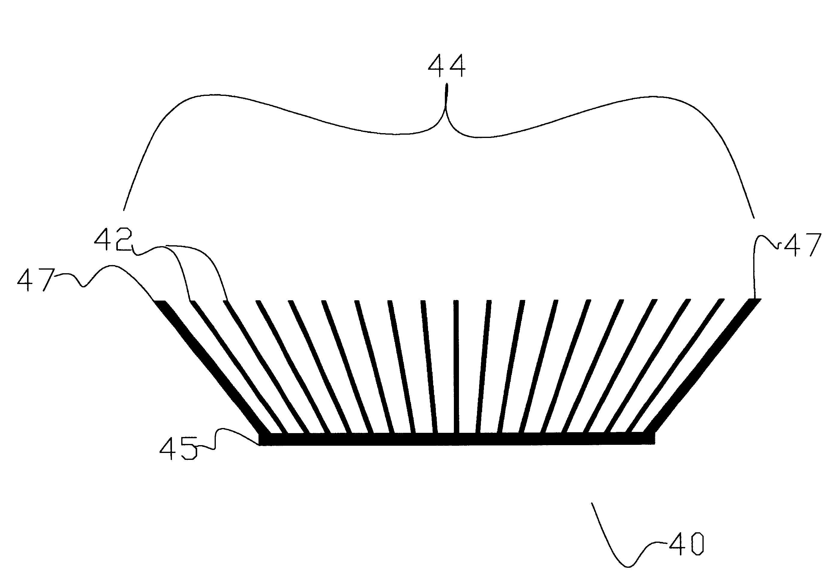
In this disclosure, the term "fin" (also called a "plate" or "flat fin") refers to a substantially planar heat exchanging member that extends at an angle from a base. Such a base may support a number of plate fins, in which case, "channels" are defined as the spacing between adjacent fins. The area within and immediately about the cluster of plate fins is referred to as the "fin field." It should be understood that the term "fluid" as used herein refers to both liquids and gases. The flow of fluid across the fin field can be created using known means such as fans and natural convection.

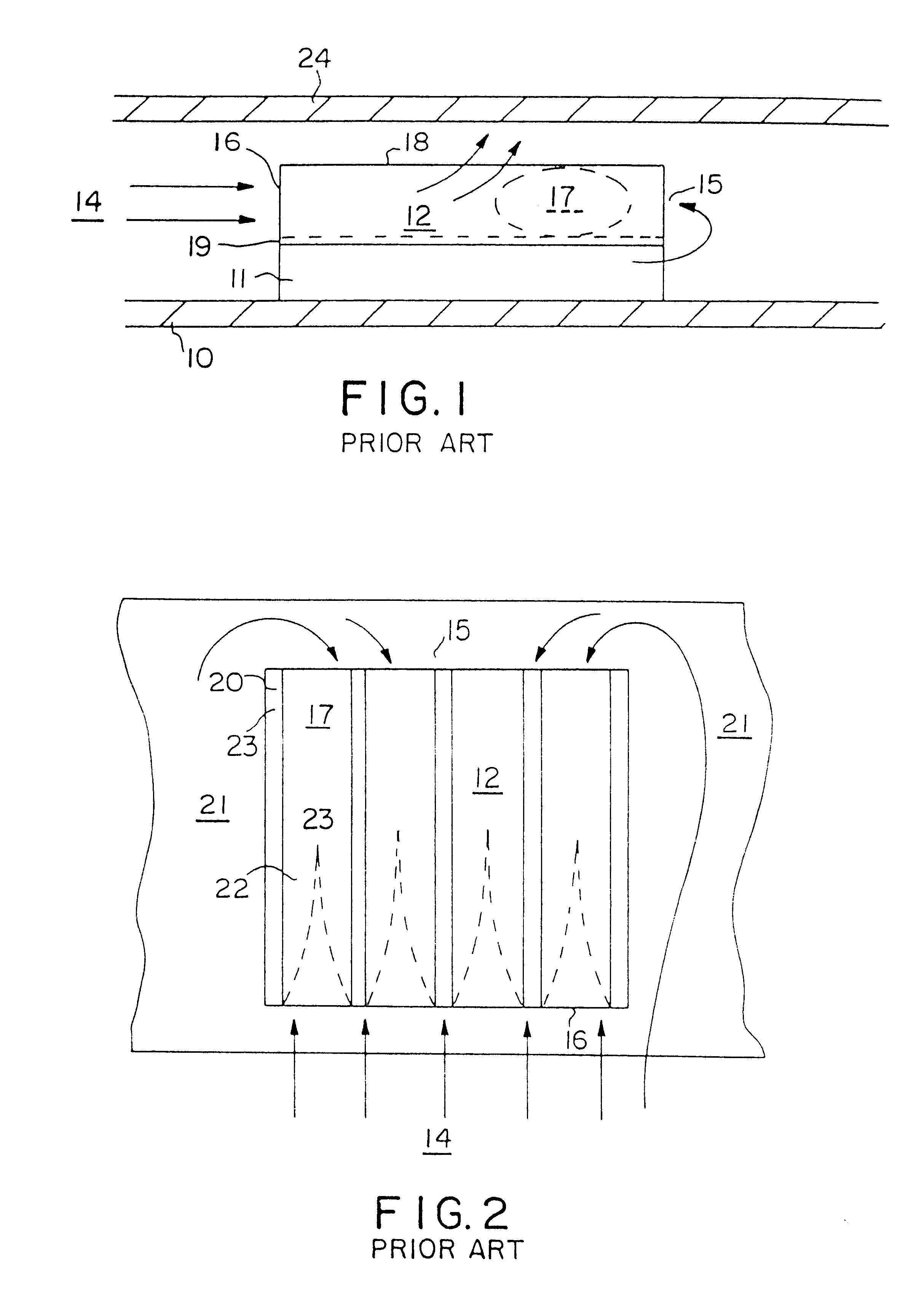
Referring now to the drawings, FIGS. 1 and 2 illustrate a prior art configuration of a heat generating component 11 mounted to a printed circuit board (PCB) 10 and adjacent to another PCB 24. A prior art heat exchanger having individual plate fins 20 affixed to a base 19 is mounted to the component 11. The plate fins 20 define a fin field 12, and channels 23 through which cooling fluid 13 flows. The f...


PUM


Abstract

A novel plate fin heat exchanger adapted for high and low velocity fluid flows for dissipating heat from a heat generating component. The heat exchanger comprises an array of fins being affixed to and in thermal communication with a thermally conductive base, wherein the fins are arranged in a fan tail configuration for minimizing flow bypass, and further providing reduced thermal resistance for fluid passing through the fin field. The fins are affixed to and in thermal communication with the base at an acute angle, such that the effective width of the array of fins exceeds the width of the base. The enlarged effective width of the fin array in comparison to conventional heat exchanger provides an increased volume for fluid flow, thereby allowing a greater volume of fluid to enter the fin field and a greater surface area of plate fins for cooling the fluid passing through the heat exchanger. In addition, the heat exchanger comprises a fin density of at least ten fins per inch or greater of base length thereby providing a narrow channel heat exchanger with a fan tail. The aspect ratio of the individual channels between the fins, as compared to parallel fins affixed perpendicular to the base through an extrusion method, generates a reduced pressure drop across the heat exchanger. Accordingly, the heat exchanger of the present invention expands the envelope of cooling performance provided by fluid flow over an array of thermally conductive plates.

Description

1. Field of the InventionThis invention relates to an apparatus and method of cooling a heat producing electronic component. More particularly, this invention relates to a novel configuration and design for a heat exchanger providing an apparatus and method for managing low velocity fluid flow. The invention thereby expands the envelope of cooling performance provided by fluid flow over plates.2. Discussion of Related ArtIt is important to dissipate the heat produced by electrical devices in order to extend the useful life of these devices. Heat dissipation is particularly important in the case of high-power electronic components, such as microprocessors and lasers, which generate a relatively high amount of heat in a relatively small area. Conventional heat sink devices typically utilize an array of extended surfaces, such as fins, integrally formed on a common base. The array of extended surfaces project into an ambient fluid surrounding the device. The base is placed in thermal i...

Claims


Application Information

Patent Timeline
Patent Type & Authority Patents(United States)
IPC IPC(8): F28F3/00F28F3/02H01L23/367H01L23/34H01L23/467
CPCF28F3/02H01L23/3672H01L23/467F28F2215/10H01L2924/0002H01L2924/00
Inventor TAVASSOLI, BAHMAN
Owner ADVANCED THERMAL SOLUTION
Why Eureka
Try Eureka