
Three-Axis Adjustable Rod Holder

a three-axis adjustable, rod holder technology, applied in the direction of waterborne vessels, other angling devices, vessel construction, etc., can solve the problems of not being well oriented to support the rod holder, the rod tip is above the water line, and the most available devices offer limited options or angular ranges of adjustment, etc., to achieve the effect of improving stability, reducing splashing and reducing the height of the rod tip

Active Publication Date: 2020-04-02
MCMENAMY JAMES ROBERT +1
View PDF0 Cites 4 Cited by
  • Summary
  • Abstract
  • Description
  • Claims
  • Application Information

AI Technical Summary

Benefits of technology

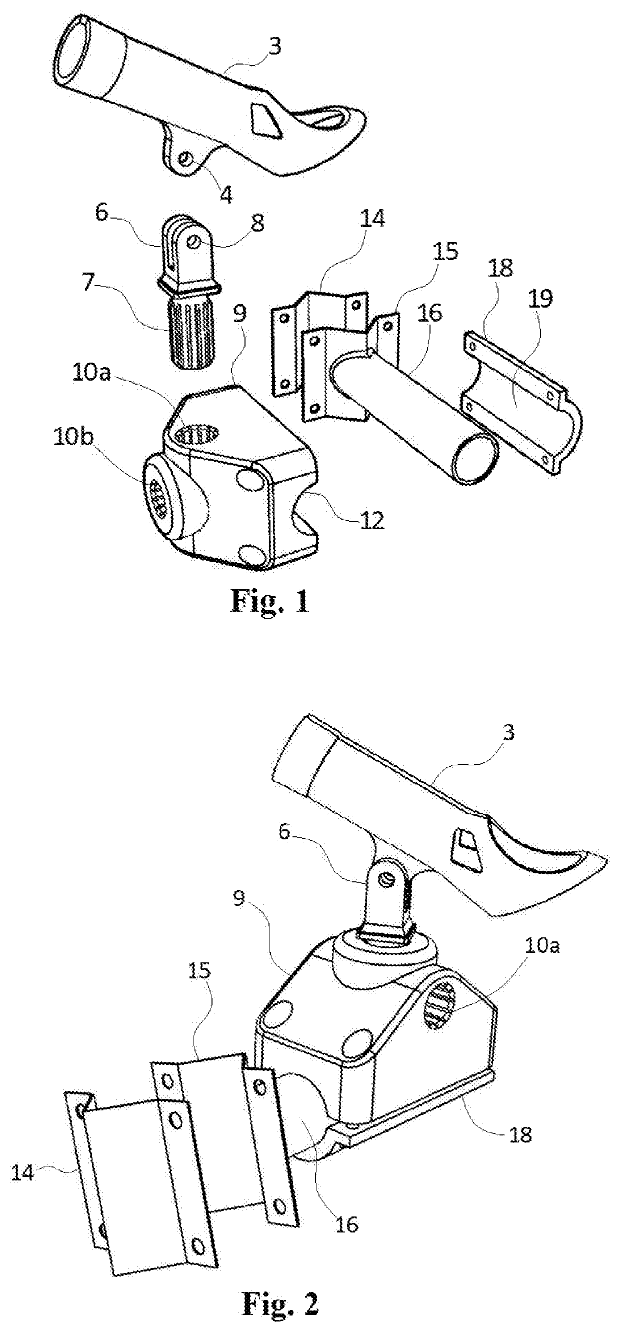
The invention is a device that allows fishing poles to be adjustably mounted on railings, stanchions, and other tube structures of a vessel. The device can be attached at any angle and offers a pivot axis that can be adjusted to be perpendicular to the water, regardless of the angle of the railing. This makes it easy to hold the pole at a comfortable angle for fishing. The device is also easy to install and detach without permanent modification of the vessel, and can be used with various attachment affords produced by manufacturers and designers in the fishing and boating industry. This allows for flexibility in the placement of the fishing pole holders on the vessel.

Problems solved by technology

Most available devices offer limited options or angular ranges of adjustment.
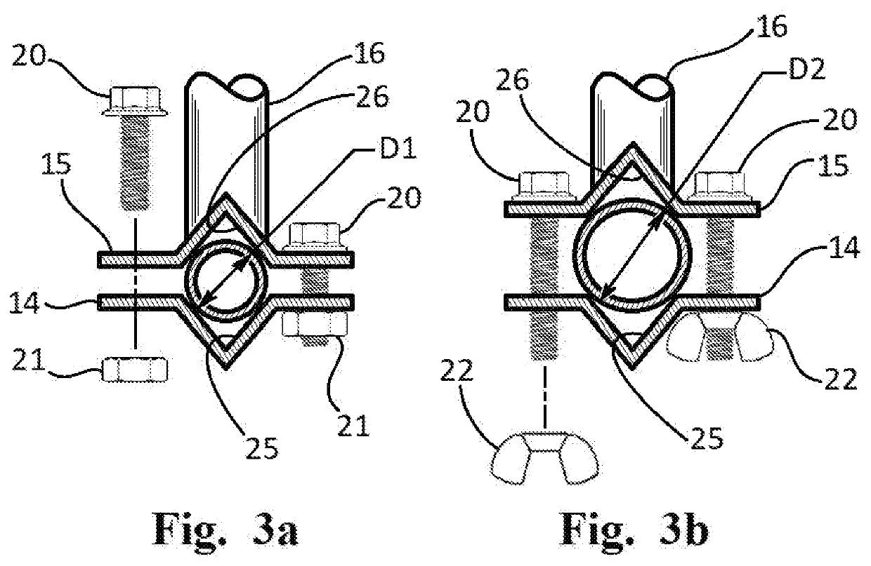
Railings, stanchions or other tube structures afford attachment sites for fishing pole holders adapted to clamp to tubes, but these tube structures, being shaped in accordance with their primary functions (e.g a railing to prevent falls overboard, a spar, boom, or stanchion which acts as a flagpole or a mast for a hoist, etc.) may not be well oriented to support a clamp at an advantageous or a preferred angle for supporting a fishing pole.
For flared hulls which are most common, this means that the positioning axis for the rod or rod holder inclines away from the user so that if the rod holder is rotated in such a device the height of the rod tip above water is often not only not constant throughout its subtended arc, but deleteriously drops as the rod is oriented perpendicular to the railing.

Method used


Image

  • Three-Axis Adjustable Rod Holder
  • Three-Axis Adjustable Rod Holder

Examples


Embodiment Construction

of CERTAIN EMBODIMENTS

[0015]While various aspects and features of certain embodiments have been summarized above, the following detailed description illustrates a few exemplary embodiments in further detail to enable one skilled in the art to practice such embodiments. The described examples are provided for illustrative purposes and are not intended to limit the scope of the invention.

[0016]In the following description, for the purposes of explanation, numerous specific details are set forth in order to provide a thorough understanding of the described embodiments. It will be apparent to one skilled in the art, however, that other embodiments of the present invention may be practiced without some of these specific details. Several embodiments are described herein, and while various features are ascribed to different embodiments, it should be appreciated that the features described with respect to one embodiment may be incorporated with other embodiments as well. By the same token, ...


PUM


Abstract

An adjustable bracket that clamps onto a first axis includes a rod defining a second, orthogonal axis upon which a pivot block is mounted. The pivot block includes two perpendicular splined apertures which may receive a fishing rod holder that has a splined shaft to fix the azimuth orientation of the rod holder in the pivot block.The fishing rod holder has a clevis which receives a perforated ear of a rod retaining tube. A fastener clamps the retaining tube in the clevis at a desired elevation angle. The retaining tube has other features which may coddle a reel mounted on a fishing rod. The azimuth options of the spline interface and the elevation adjustment of the clevis joint provide second and third adjustable axes for orienting a fishing pole from an attachment point on any railing or stanchion or post on a vessel.

Description

CROSS REFERENCE TO RELATED APPLICATION[0001]This non-provisional utility application claims the benefit of and priority to U.S. Provisional Patent Application 62 / 737,760 “Three-Axis Adjustable Rod Holder,” filed 27 Sep. 2018. The entire content of U.S. Provisional Patent Application 62 / 737,760 “Three-Axis Adjustable Rod Holder,” filed 27 Sep. 2018 is hereby incorporated into this document by reference.COPYRIGHT STATEMENT[0002]A portion of the disclosure of this patent document contains material that is subject to copyright protection. The copyright owner has no objection to the facsimile reproduction by anyone of the patent document or the patent disclosure as it appears in the Patent and Trademark Office patent file or records, but otherwise reserves all copyright rights whatsoever.FIELD[0003]The invention relates adjustable mounting of fishing poles on railings, stanchions, poles or other tube structures of a vessel.BACKGROUND[0004]People who fish from boats using fishing poles of...

Claims


Application Information

Patent Timeline
Patent Type & Authority Applications(United States)
IPC IPC(8): A01K97/10B63B17/00
CPCB63B17/00A01K97/10
Inventor MCMENAMY, JAMES ROBERTMCMENAMY, JAMES BRUCE
Owner MCMENAMY JAMES ROBERT
Learn More