
Combined outrigger holder and fishing rod holder

a combination of outrigger holder and fishing rod technology, applied in fishing, special-purpose vessels, machine supports, etc., can solve the problems of not being able to adjust the positioning of outriggers, and being used for one device at a tim

Active Publication Date: 2007-11-20
EASTERN METAL SUPPLY
View PDF68 Cites 48 Cited by
  • Summary
  • Abstract
  • Description
  • Claims
  • Application Information

AI Technical Summary

Problems solved by technology

A problem with such holders is that they can only be used for one device at a time.
Furthermore, they are not adjustable for positioning the outriggers in various inboard, parallel, outboard, and elevated positions.

Method used


Image

  • Combined outrigger holder and fishing rod holder
  • Combined outrigger holder and fishing rod holder
  • Combined outrigger holder and fishing rod holder

Examples


Embodiment Construction

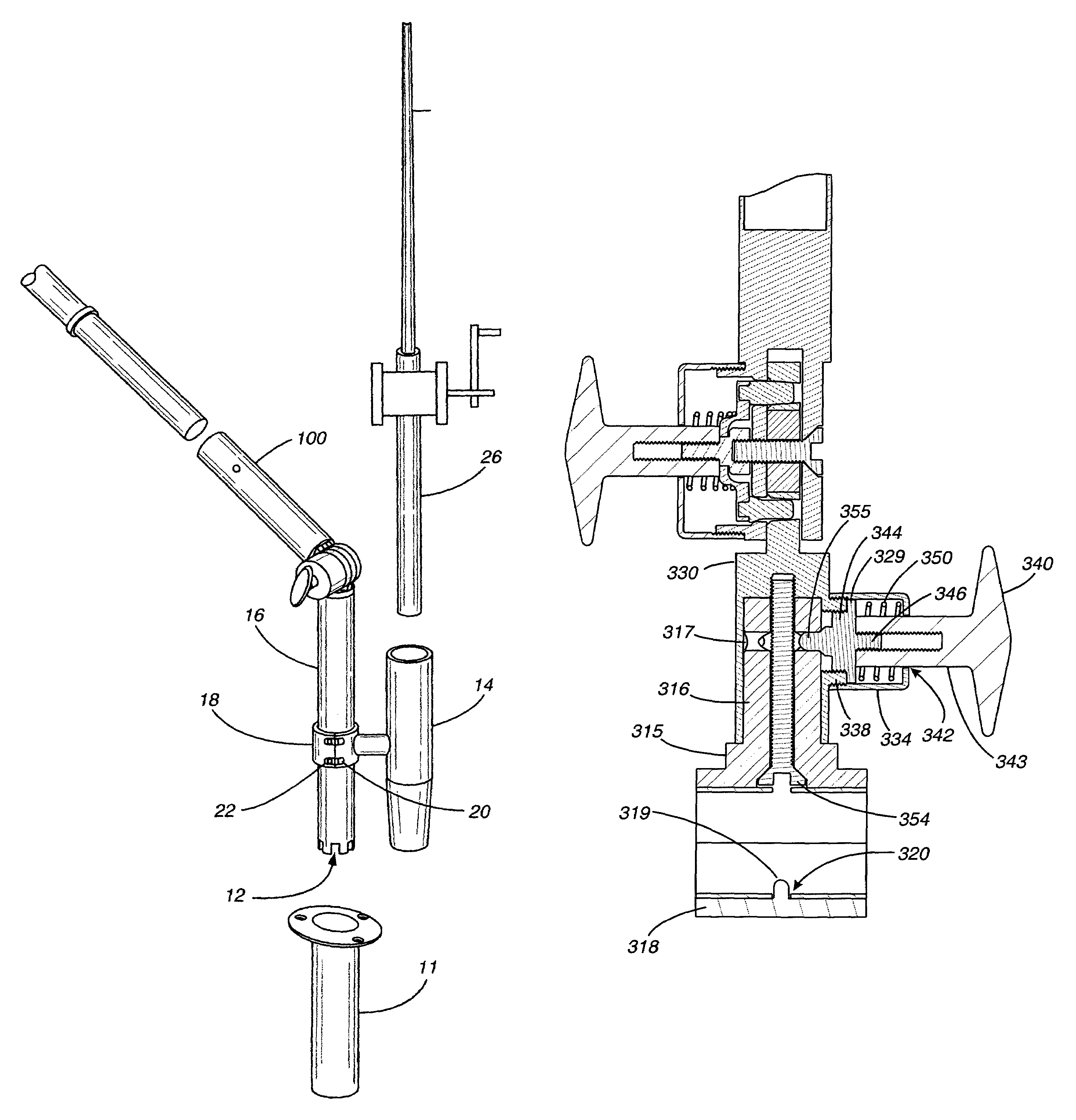
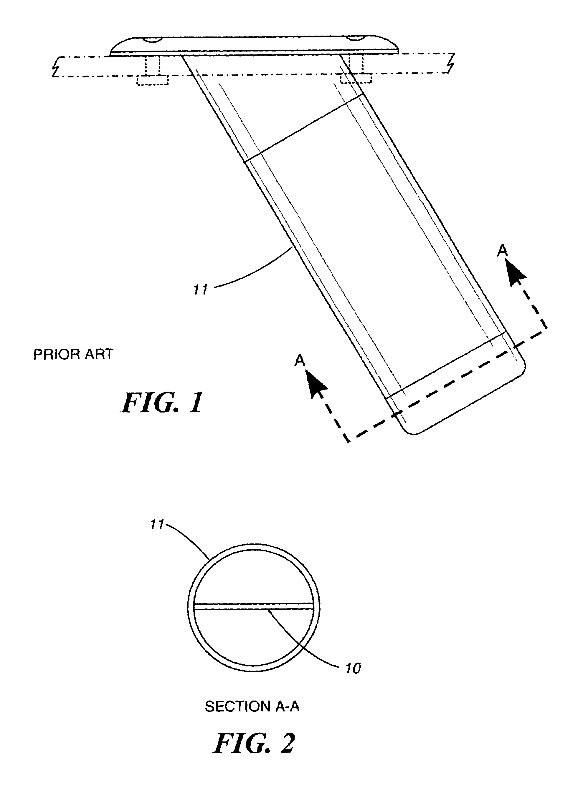
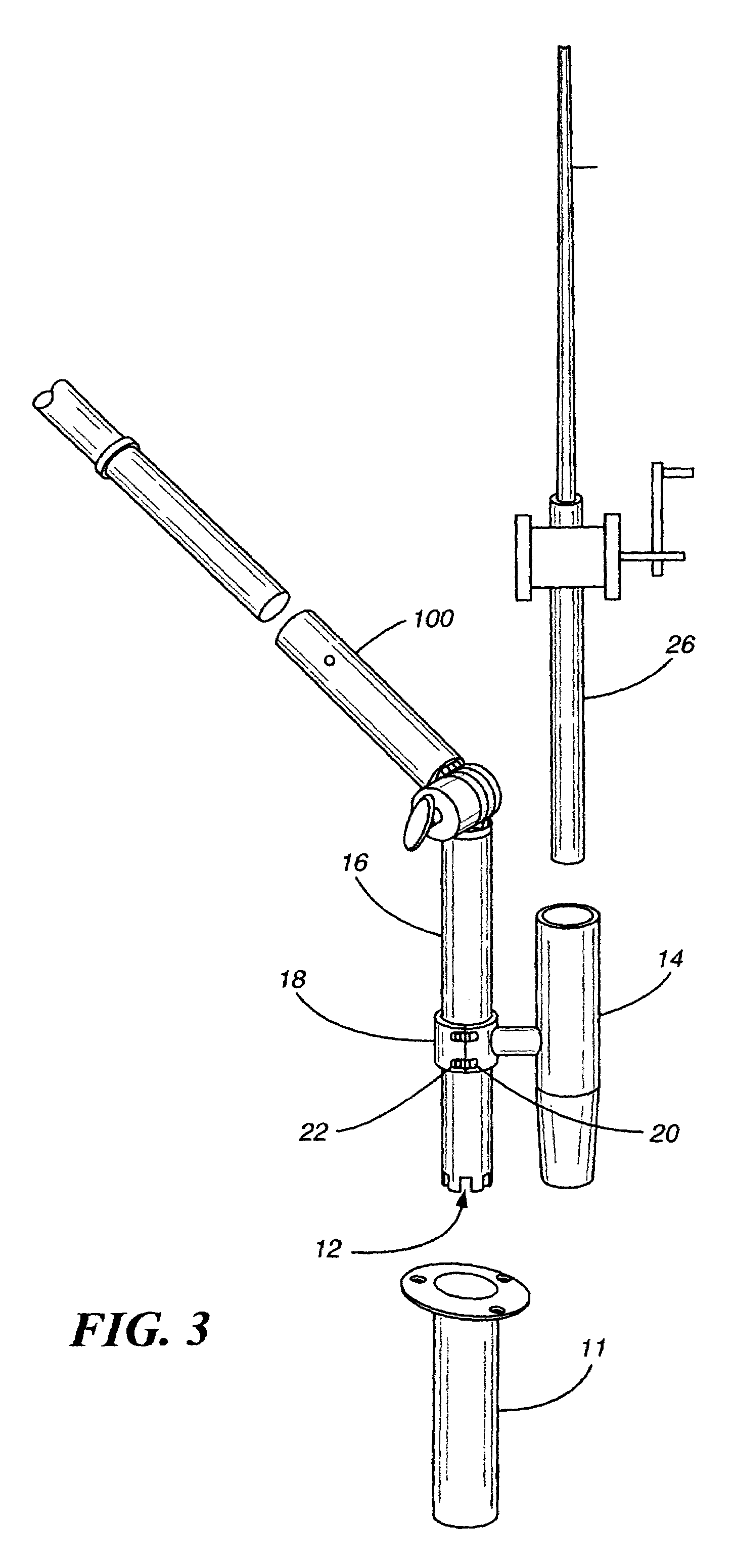
[0019]Referring to the Figures, FIG. 1 shows a prior art fishing rod holder 11 for permanent installation in a gunnel of a fishing boat. Taking a section as indicated by the lines and arrows A-A in FIG. 1, the usual holder structure would have a pin 10 across the inside near the bottom. The purpose of the pin 10 is to accommodate the notches in the bottom of a fishing rod. We provide similar notches, designated generally 12FIG. 3 in the bottom of an outrigger holder 16. Thus the rod or the outrigger holder can be moved, i.e. rotated, to a number of fixed positions; wherein the notches embrace the pin and the structure will not rotate.

[0020]In accordance with our invention, a clamp-on rod holder 14 is provided; which can be clamped on to the outrigger holder 16 by any suitable clamp means 18. The clamp means 18 is most preferably release able as by means of screws 20 fitted into bosses 22. Thus the fishing rod holder 11 can now accommodate our outrigger holder 16 and simultaneously p...


PUM


Abstract

An apparatus is described, combining a portable outrigger holder with a fishing rod holder; so that both can be moved to a plurality of positions in both a horizontal plane and a vertical plane.

Description

CROSS REFERENCE TO RELATED APPLICATIONS[0001]This application claims the benefit of the filing date of our prior application Ser. No. 11 / 237,605 filed Sep. 27, 2005, entitled “Combined outrigger holder and fishing rod holder”; now abandoned and the benefit of the filing date of our prior application Ser. No. 60 / 614,633 filed Sep. 29, 2004, entitled “Combined outrigger holder and rod holder” referenced therein, and the applications referenced therein, Ser. No. 10 / 801,275, filed Mar. 16, 2004, entitled “T-TOP OUTRIGGER HOLDER APPARATUS;” now U.S. Pat. No. 7,197,845 and application Ser. No. 60 / 455,982, filed Mar. 19,2003, the disclosures of which are incorporated herein by reference as if fully set forth.BACKGROUND OF THE INVENTION[0002]1. Technical Field[0003]This invention relates to fishing equipment and, more particularly, to fishing rod and outrigger holders for use on boats to hold either the outrigger or the rod or both.[0004]2. Description of the Prior Art[0005]In the prior art...

Claims


Application Information

Patent Timeline
Patent Type & Authority Patents(United States)
IPC IPC(8): A01K97/10
CPCA01K97/10A01K91/08
Inventor WILCOX, ROGERWILCOX, SCOTT A.
Owner EASTERN METAL SUPPLY
Learn More