Endoscope

a technology of endoscope and endoscope, which is applied in the field of endoscope, to achieve the effect of improving the draining function of injected water

Inactive Publication Date: 2011-05-12
FUJIFILM CORP
View PDF4 Cites 90 Cited by
  • Summary
  • Abstract
  • Description
  • Claims
  • Application Information

AI Technical Summary

Benefits of technology

[0022]According to the present invention, since there are the inclined plane which is disposed the position facing the fluid injection nozzle, and the back-flow prevention member which is provided on the counter side from the fluid injection nozzle across the observation window so as to prevent that fluid injected fr

Problems solved by technology

However, in the endoscopes of Japanese Laid-open Patent Publication No. 2003-210388 and Japanese Laid-open Patent Publication No. 03-165731, since the inclined plane whose height gradually becomes higher from the flat surface to the top surface of the observation window is f

Method used


Image

  • Endoscope
  • Endoscope
  • Endoscope

Examples


first embodiment

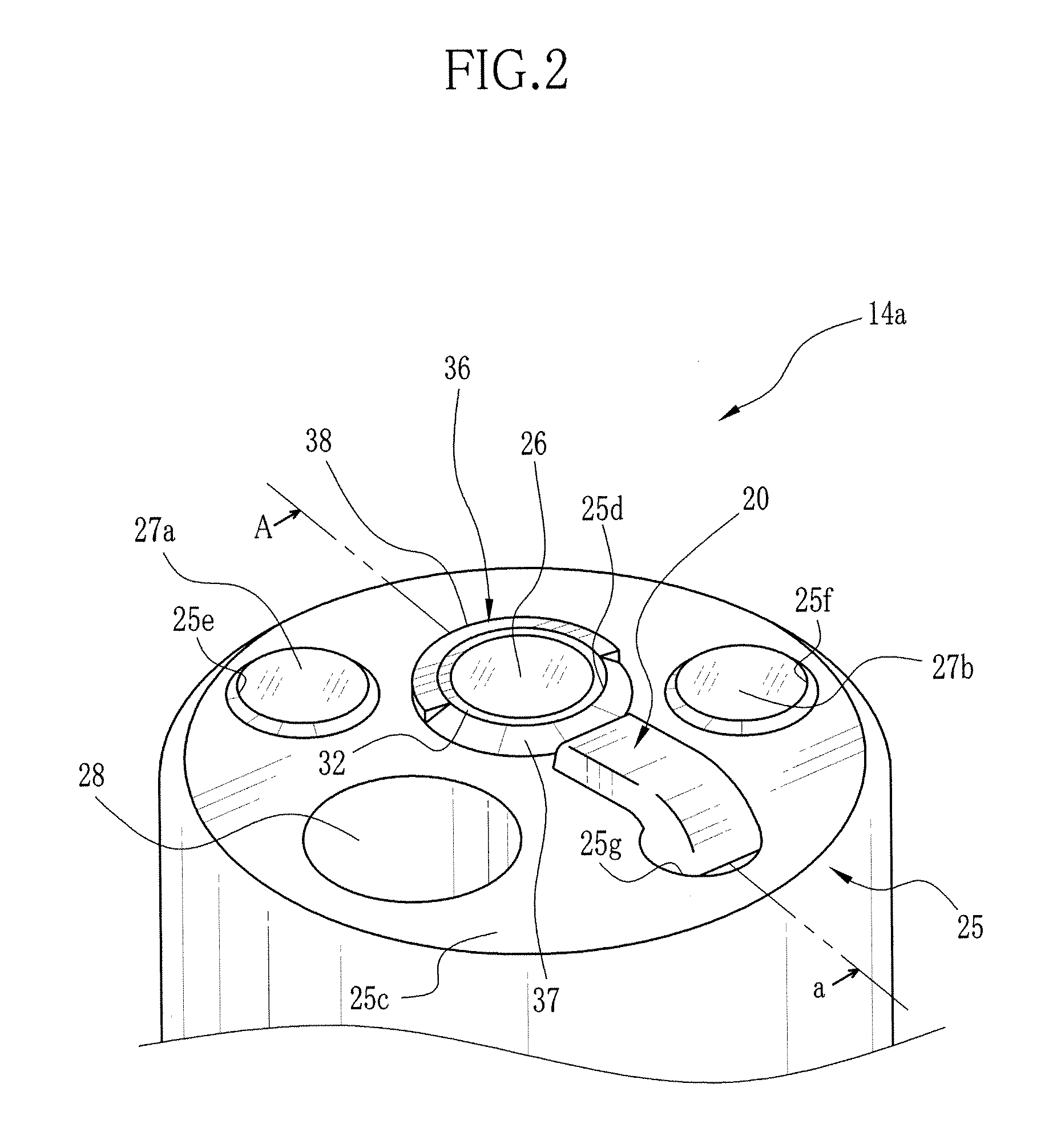
[0071]Note that also in the first embodiment in which the vertical plane 38 is formed as the back-flow prevention member, there becomes an edge portion (see FIG. 2) at the boundary between the first inclined plane 37 and the vertical plane 38 . The edge portion may be planed off to form a link surface which smoothly links between the first inclined plane 37 and the vertical plane 38.

[0072]In the first and second embodiments, the first inclined plane 37 and the back-flow prevention member are integrally formed with the ring projection. However, as a head section 50 of a third embodiment illustrated in FIGS. 8 and 9, a circular arc projection 51 having the first inclined plane 37 may be provided, and the peripheral surface 32a of the lens barrel 32 holding the observation window 26 may be exposed from a cut-out 52 formed on the circular arc projection 51, as the back-flow prevention member.

[0073]In the head section 50 of the third embodiment, between the periphery of the observation w...

second embodiment

[0075]Note that in this embodiment, the peripheral surface 32a is the vertical plane. However, the peripheral surface 32a may have the inclination same as of the second inclined plane 42 of the In addition, instead of the peripheral surface 32a, the flange of the observation window 26 may become the back-flow prevention member.

[0076]As a variation of the third embodiment illustrated in FIGS. 10 and 11, on the flat surface 25c, a recessed edge 55 may be formed such that the back-flow prevention member side of the flat surface 25c with reference to the boundary between the back-flow prevention member and the first inclined plane 37 has a height lower than that of the first inclined plane side of the flat surface 25c. The recessed edge 55 covers an area from a step 56 as the boundary with the rest of the flat surface 25c to the outer periphery of the protective cover 25. According to this configuration, as illustrated in FIG. 11, a water drop 53 remains on the recessed edge 55 which h...

fourth embodiment

[0080]As a fourth embodiment illustrated in FIG. 13, on a head section 60, there are the first inclined plane 37 and a back-flow prevention member 62. The back-flow prevention member 62 is formed on a projection 61 having a shape of a ring or a circular arc which is provided separately from the protective cover 25. The projection 61 is fixed on the flat surface 25c with use of an adhesive or the like. As the above-described ring projection 41, in case the second inclined plane 42, whose outer diameter gradually decreases from the periphery of the observation window 26 to the flat surface 25c, is formed integrally with the protective cover 25 and is used as the back-flow prevention member, since the inclination directions of the first and second inclined planes 37 and 42 are opposite to each other, a construction of a forming die for them becomes complicated, which causes an increase in a cost. However, in the embodiment of FIG. 13 in which the back-flow prevention member is the memb...


PUM


Abstract

On a head section connected to a distal end of an inserter of an endoscope, an air/water nozzle, an observation window and a ring projection are provided. On the ring projection, a first inclined plane and a vertical plane are formed. The first inclined plane inclines such that the outer diameter thereof gradually decreases from the top surface of the observation window toward a flat surface. The vertical plane is positioned at the counter side from the air/water nozzle across the observation window. Fluid injected from the air/water nozzle hits the first inclined plane and spreads to pass over the observation window. The vertical plane stops backflow of a water drop on the flat surface toward the observation window, so as to prevent that the water drop reaches on the top surface of the observation window.

Description

BACKGROUND OF THE INVENTION[0001]1. Field of the Invention[0002]The present invention is related to an endoscope which comprises a fluid injection nozzle which injects fluid to an observation window.[0003]2. Description of the Related Arts[0004]An endoscope comprises an observation window for taking image light of a subject, and a fluid (air / water) injection nozzle which injects fluid to the observation window, at a head of an inserter for the subject. The observation window and the fluid injection nozzle are provided on a flat surface which is approximately perpendicular to the axial direction of the inserter. The observation window is provided such that a surface as a light entrance surface is protruded a certain height from the flat surface. On the top surface of the observation window, secretion and dirt from the subject are adhered. To wash them, the fluid injection nozzle injects water from an injection orifice toward the observation window. Then air is injected from the injec...

Claims


Application Information

Patent Timeline
IPC IPC(8): A61B1/04
CPCA61B1/05A61B1/126A61B1/127
Inventor KOGA, TAKEHIKOSUZUKI, ISSEI
Owner FUJIFILM CORP
Why Eureka
Try Eureka