Retaining wall block

a technology of retaining walls and blocks, applied in the direction of excavations, embankments, construction, etc., can solve the problems of many segmental wall designs that cannot accommodate anchoring posts, and it is not always feasible to extend geosynthetic reinforcement behind the wall, so as to reduce or zero predetermined setbacks

Inactive Publication Date: 2007-01-30
MELLON BANK N A
View PDF10 Cites 90 Cited by
  • Summary
  • Abstract
  • Description
  • Claims
  • Application Information

AI Technical Summary

Benefits of technology

[0020]Preferably the block further comprises third and fourth pin holes each disposed in the body portion and opening onto the top face for receiving a pin with a free end of the pin protruding beyond the top face, the third and fourth pin holes being disposed on the first and second planes forward of the first and second pin holes so as to provide a reduced or zero predetermined setback.

Problems solved by technology

Existing segmental wall block designs have proven quite versatile, but have limitations in constructing certain structures.
Many segmental wall designs are not able to accommodate the anchoring posts for such structures.
Similarly, it is not always feasible to extend geosynthetic reinforcement behind a wall.
Most existing modular walls blocks cannot be constructed through the use of grout and rebar reinforcement.

Method used


Image

  • Retaining wall block
  • Retaining wall block
  • Retaining wall block

Examples


Embodiment Construction

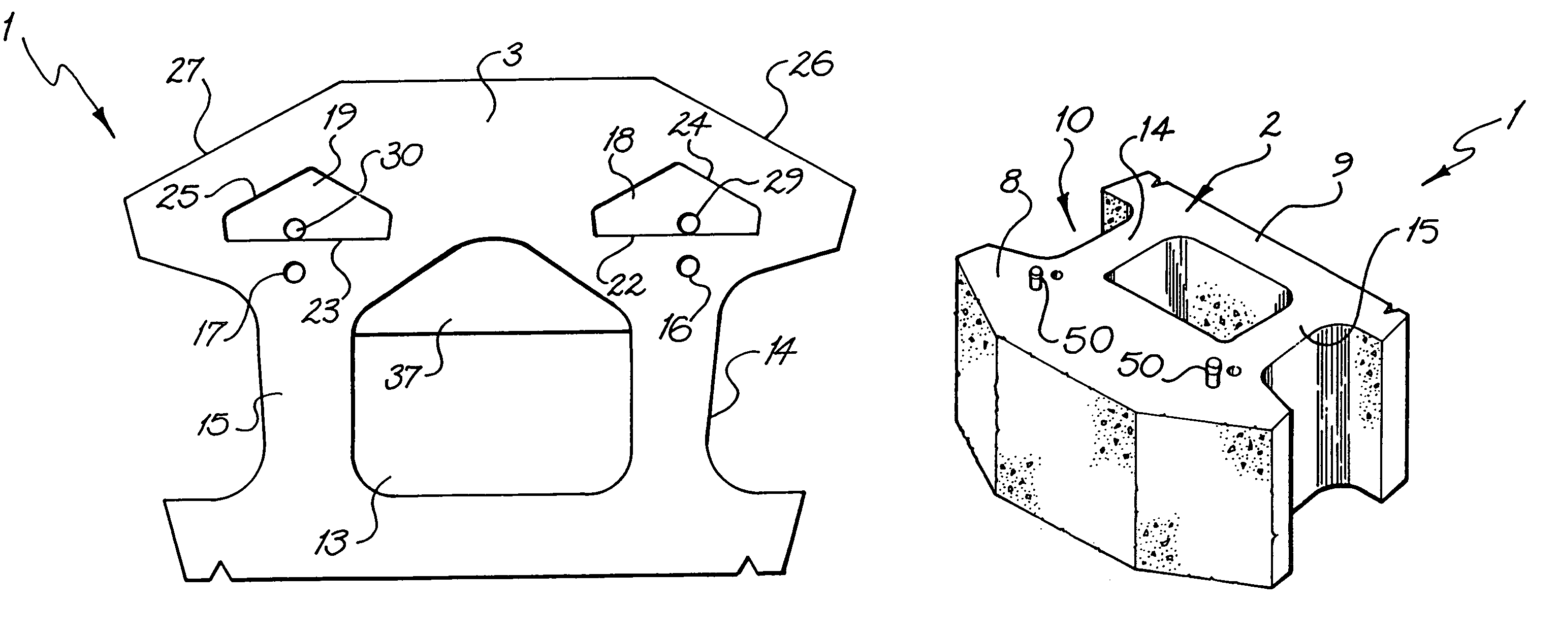
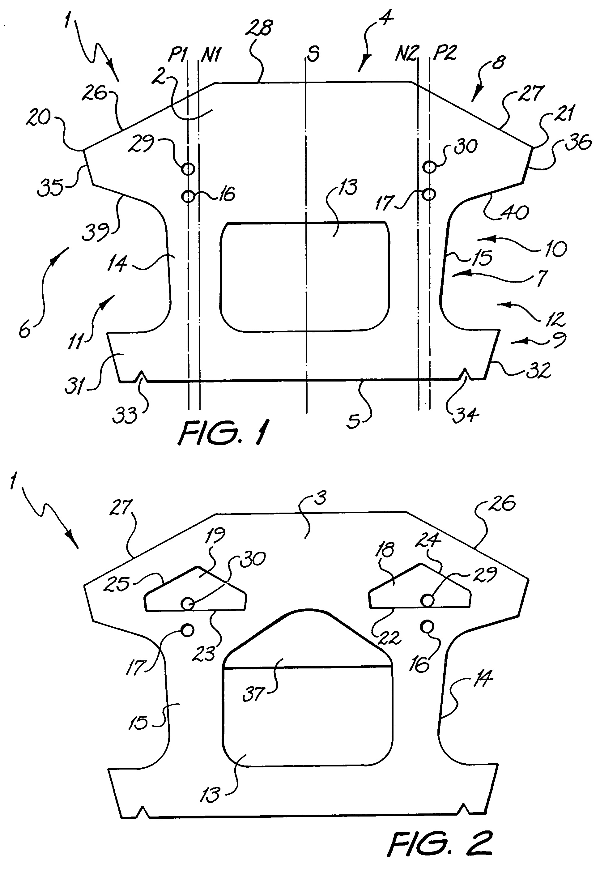
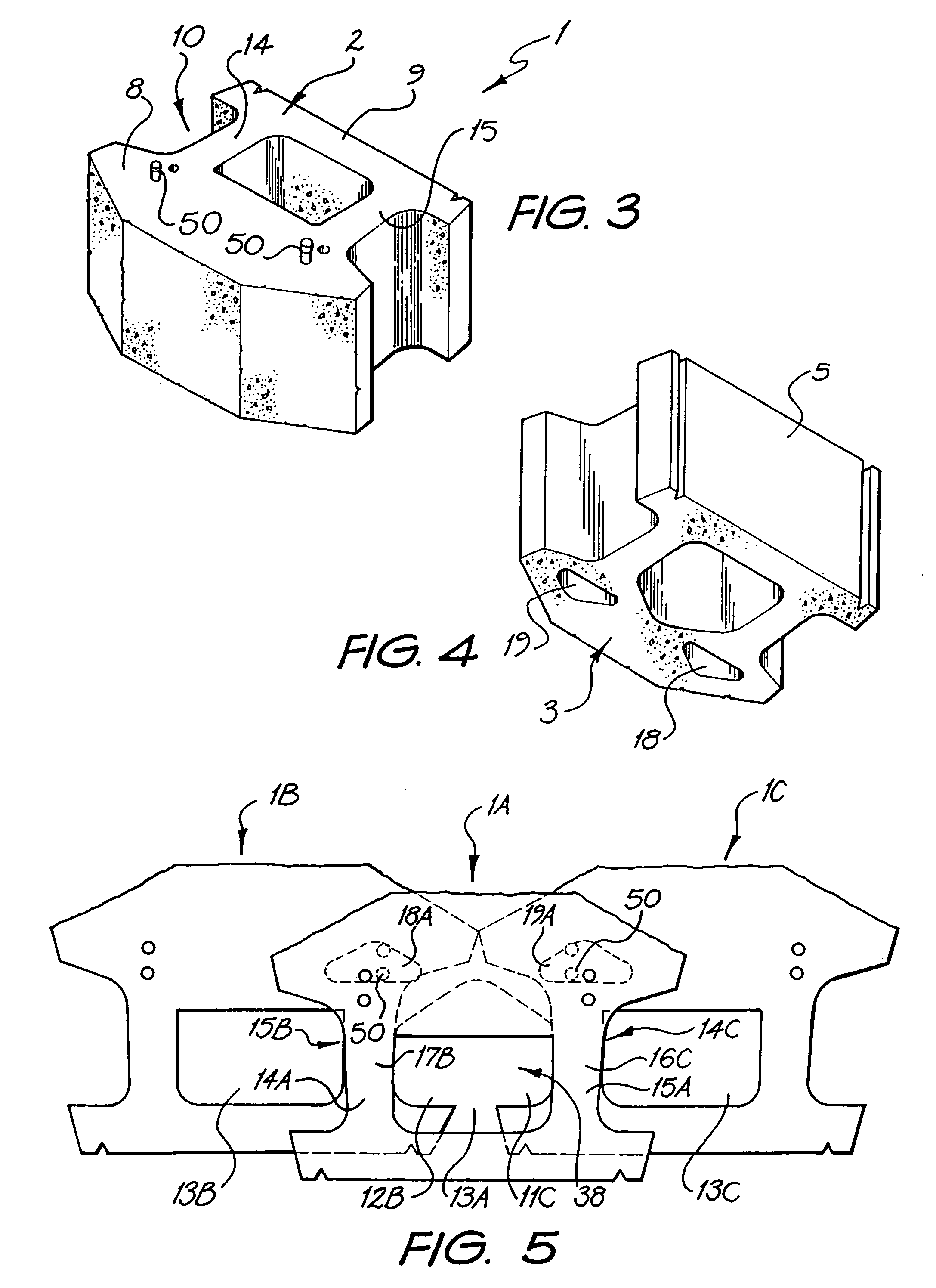
[0046]Referring to FIGS. 1 to 4 there is shown retaining wall block 1 according to a preferred embodiment of the present invention. Block 1 is made of a rugged, weather resistant material, preferably pre-cast concrete. Other suitable materials are plastic, reinforced fibers, wood, metal and stone. Block 1 has parallel top face 2 and bottom face 3, front face 4, rear face 5 and first and second side wall faces 6 and 7. Front face 4 and rear face 5 each extend from top face 2 to bottom face 3 and side wall faces 6, 7 extend from top face 2 to bottom face 3 and from front face 4 to rear face 4. Block 1 is generally symmetrical about vertical plane of symmetry S.

[0047]The integrally formed block 1 takes the form of body portion 8, head portion 9 and neck portion 10 connecting body portion 8 and head portion 9. Front face 4 forms part of body portion 8, while rear face 5 forms part of head portion 9. The body, head and neck portions 8, 9, and 10 each extend between top and bottom faces 2...


PUM


Abstract

A retaining wall block (1) has parallel top and bottom faces (2, 3), a front face (4), a rear face (5), first and second side wall faces (6, 7) and a vertical plane of symmetry (S) extending between the front and rear faces (4, 5). The block (1) is formed as a body portion (8) including the front face (4), a head portion (9) including the rear face (5) and a neck portion (10) connecting the body portion (8) and the head portion (9). The body, head and neck portions (8, 9, 10) each extend between the top and bottom faces (2, 3) and between the first and second side wall faces (6, 7). An opening (13)′ extends through the neck portion (10) from the top face (2) to the bottom face (3), dividing the neck portion (10) into first and second neck wall members (14, 15) extending rearwardly from the body portion (8) to the head portion (9). First and second pin holes (16 and 17) are each disposed in the body portion (8) and open onto the top face (2) for receiving a pin (50, 51) with a free end of the pin protruding beyond the top face. First and second pin receiving cavities (18, 19) are each disposed in the body portion (8) and open onto the bottom face (3) for receiving the free end of a pin (50, 51) received in a pin hole (16 and 17) of an adjacent block (1) disposed therebeneath so as to interlock the blocks (1) with a predetermined setback. The neck wall members (14, 15), pin holes (16 and 17) and pin receiving cavities (18, 19) are positioned such that a first plane (P1) extending parallel to the plane of symmetry (5) passes through the first pin receiving cavity (18), first pin hole (16) and first neck wall member (14) and a second plane (P2) extending parallel to the plane of symmetry (5) passes through the second pin receiving cavity (19), second pin hole (17) and second neck wall member (15).

Description

FIELD OF THE INVENTION[0001]The present invention is directed to the field of retaining walls and blocks used to construct a retaining wall.BACKGROUND TO THE INVENTION[0002]Numerous methods and materials exist for the construction of retaining walls. Such methods include the use of natural stone, poured in place concrete, masonry, and landscape timbers or railroad ties. In recent years, segmental concrete retaining wall units which are dry stacked (i.e., built without the use of mortar) have become a widely accepted product for the construction of retaining walls. Examples of such products are described in U.S. Pat. No. Re. 34,314 (Forsberg '314) and U.S. Pat. No. 5,294,216 (Sievert). Such products have gained popularity because they are mass produced, and thus relatively inexpensive. They are structurally sound, easy and relatively inexpensive to install, and couple the durability of concrete with the attractiveness of various architectural finishes.[0003]The retaining wall system ...

Claims


Application Information

Patent Timeline
Patent Type & Authority Patents(United States)
IPC IPC(8): E02D5/00E02D17/18E02DE02D17/20E02D29/02
CPCE02D29/0225E02D29/025E02D2600/20E02D29/02E02B3/14E02D17/20
Inventor MACDONALD, ROBERT A.RACE, ROBERT J.
Owner MELLON BANK N A
Why Eureka
Try Eureka