Cable grommet with ball and socket

a technology of socket joint and grommet, which is applied in the field of grommets, can solve the problems of inability to install and assembly is not water resistant, and achieve the effect of strengthening the cavity and increasing the thickness of the hemispherical cavity

Inactive Publication Date: 2009-05-19
THOMPSON DAVID M
View PDF17 Cites 90 Cited by
  • Summary
  • Abstract
  • Description
  • Claims
  • Application Information

AI Technical Summary

Benefits of technology

[0017]The cup members each have an outer periphery and a semicircular flange extending around the outer periphery from a flange upper end at the vertical plane to a flange lower end at the vertical plane. Each flange lies in a plane perpendicular to the socket central axis. Each flange has a predetermined thickness. Each cup member has an upper tab and a lower tab projecting transversely through the vertical plane from the flange upper and lower ends respectively. Each tab has a thickness of generally half the flange predetermined thickness. The upper and lower tabs of each cup member are adapted to overlap the upper and lower tabs of the opposed cup member respectively. The overlapping tabs lie flush with the flanges on the front and rear, and link together the opposed cup members. Each cup member has an upper and lower brow portion on the cavity outer surface adjacent the flange upper and lower ends respectively. The brow portions increase the thickness of the hemispherical cavity adjacent the vertical plane, thereby strengthening the cavity. Each cup member has a plurality of mounting holes through the flanges and tabs for mounting the socket on the panel.

Problems solved by technology

They cannot be installed without disconnecting one end of the cable.
The assembly is not water resistant.

Method used


Image

  • Cable grommet with ball and socket
  • Cable grommet with ball and socket
  • Cable grommet with ball and socket

Examples


Embodiment Construction

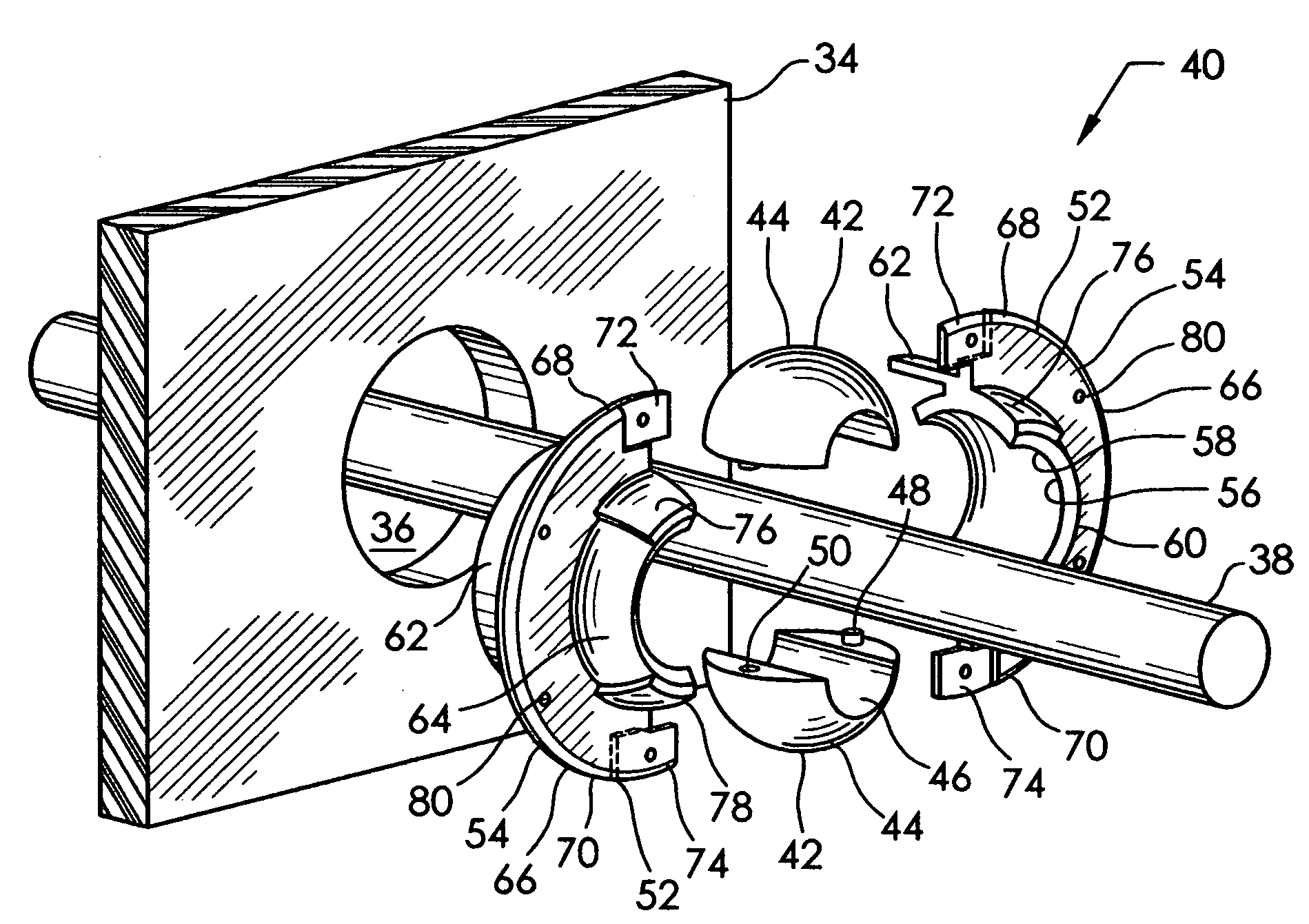
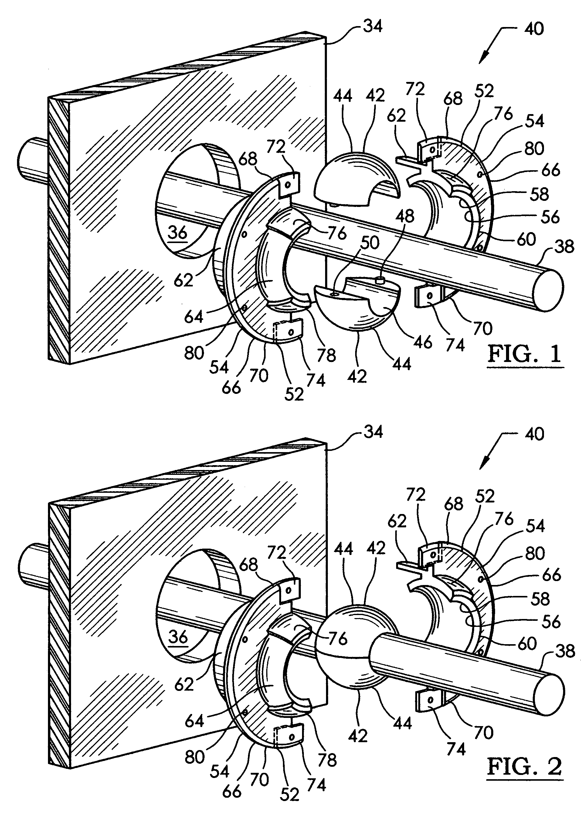
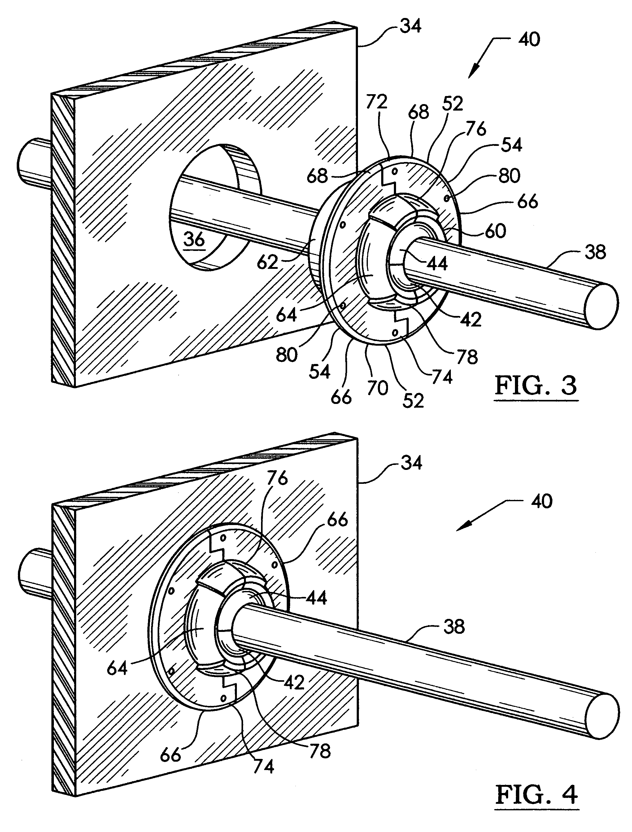
[0042]Referring now to the drawing, and especially to FIGS. 1-8 thereof, a cable grommet with ball and socket is shown at 40, and is for use in connection with a wall, bulkhead, or panel 34, and a cable, or elongated member 38. The panel 34 has a hole 36 through it, and the elongated member 38 passes through the panel hole 36. The grommet 40 comprises a ball 42 having a pair of opposed hemispherical members 44. The ball 42 has a ball central axis, and a horizontal plane aligned with the ball central axis. The hemispherical members 44 are juxtaposed along the horizontal plane. The ball 42 has at least one ball hole 46 through it, and aligned with the ball central axis. The ball hole 46 is adapted to receive the elongated member 38. One, and preferably both, of the pair of hemispherical members 44 each has at least one pin 48 projecting outward through the horizontal plane. The opposed hemispherical member 44 has at least one pin hole 50 adapted to receive the pin 48. This is to align...


PUM


Abstract

A cable grommet with ball and socket is used in connection with an elongated member passing through a hole in a panel. The ball has a pair of opposed hemispherical members juxtaposed along a ball central axis and horizontal plane. The ball has a hole through it aligned with the central axis, to receive the elongated member. A socket supports and retains the ball securely, while allowing the ball to pivot in any direction. The socket has a pair of opposed cup members, each with a hemispherical cavity therein centered on a socket central axis and vertical plane. A pilot aligns the socket with the panel hole. The cup members each have two tabs projecting transversely from a semicircular flange. The tabs of the opposed cup members overlap. Each cup member has an upper and lower thickened brow portion on the cavity adjacent the flange ends to strengthen the cavity. An adapter allows mounting the grommet in an oversized panel hole.

Description

CROSS-REFERENCE TO RELATED APPLICATIONS[0001]Not ApplicableSTATEMENT REGARDING FEDERALLY SPONSORED RESEARCH OR DEVELOPMENT[0002]Not ApplicableBACKGROUND OF THE INVENTION[0003]This invention relates to the field of grommets, and more particularly to a cable grommet having a ball and socket joint.[0004]Grommets are used to support and guide an elongated member through a hole in a panel. The elongated member can be a hose, an electrical cable or wire, a mechanical push-pull cable, a rigid rod, a fiber-optic cable, or any elongated object. The elongated member can be clamped firmly in place, or allowed to slide through the grommet. The ball can be clamped to maintain a fixed angle of penetration of the elongated member through the panel. Alternatively, the ball can be allowed to rotate within the socket, so that as the cable flexes, the ball will rotate to follow the changing angle of penetration. This is the case in some marine steering systems, where a cable angle will change to follo...

Claims


Application Information

Patent Timeline
Patent Type & Authority Patents(United States)
IPC IPC(8): H02G3/22
CPCH02G3/22Y10T16/05Y10T16/063
Inventor THOMPSON, DAVID M.
Owner THOMPSON DAVID M
Why Eureka
Try Eureka