Electric outlet with rotatable receptacles

a technology of rotatable receptacles and electric outlets, which is applied in the direction of flexible/turnable line connectors, coupling device connections, contacts, etc., can solve the problems of harmful electrical waves, power waste, and electric appliance malfunction

Inactive Publication Date: 2004-06-15
LEE JAE HA
View PDF8 Cites 96 Cited by
  • Summary
  • Abstract
  • Description
  • Claims
  • Application Information

AI Technical Summary

Benefits of technology

Another safety device is also provided for protecting the user from possible electrical hazard and organizing the electric cords around the users' area by introducing an electrical outlet with rotatable receptacles. Each of the receptacles is capable of rotating either on a top surface, top to lateral surface or both, at the same time.
Presently, the conventional electric outlets have long rectangular shape of simple design with simple function such as a main switch. Such a simple design of receptacles may not be attractive to the user or potential buyer. If one sees a dusty electric outlet in a corner of the room, one would find it objectionable.
Another type of electrical outlet with rotatable receptacles is comprised of a plurality of receptacles (21) installed in the circuitry of the power supply, with each receptacle capable of being individually rotated from top to lateral surfaces, and the rotation of each receptacle being limited to less than one revolution on a vertical plane with respect to a rotating axis for preventing the twisting, bending or breaking of the external extension cords or internal electric connections.
A safety device is installed on top of the disk type receptacle for automatically blocking a pair of prong slots when there are no devices plugged into the outlet. A cover will slide along the grooves by pushing force when a plug is plugged in. The cover will automatically block a pair of prong slots by resilient force for preventing a possible electrical hazard when a plug is pulled out.

Problems solved by technology

Thus, the power is wasted, and causes to generate the harmful electrical waves and malfunction the electric appliance.
Therefore, all appliances plugged in the same outlet are losing the electric power.
If an unwatched child is playing in the vicinity of the electric outlet with a foreign object such as a nail, hairpin, clip or metal piece, the child will be exposed to potential electric hazard.
Since most on-off switches are externally exposed, there are great possibilities for the switches to be operated unintentionally.
For example, if one were accidentally stepped on or inadvertently pushed down the switch by elbow, the electric power would be instantly turned off caused possibly a trouble.
If this were occurred during computer operation, the operator could accidentally lost his work.
Such a simple design of receptacles may not be attractive to the user or potential buyer.
If one sees a dusty electric outlet in a corner of the room, one would find it objectionable.

Method used


Image

  • Electric outlet with rotatable receptacles
  • Electric outlet with rotatable receptacles
  • Electric outlet with rotatable receptacles

Examples


first embodiment

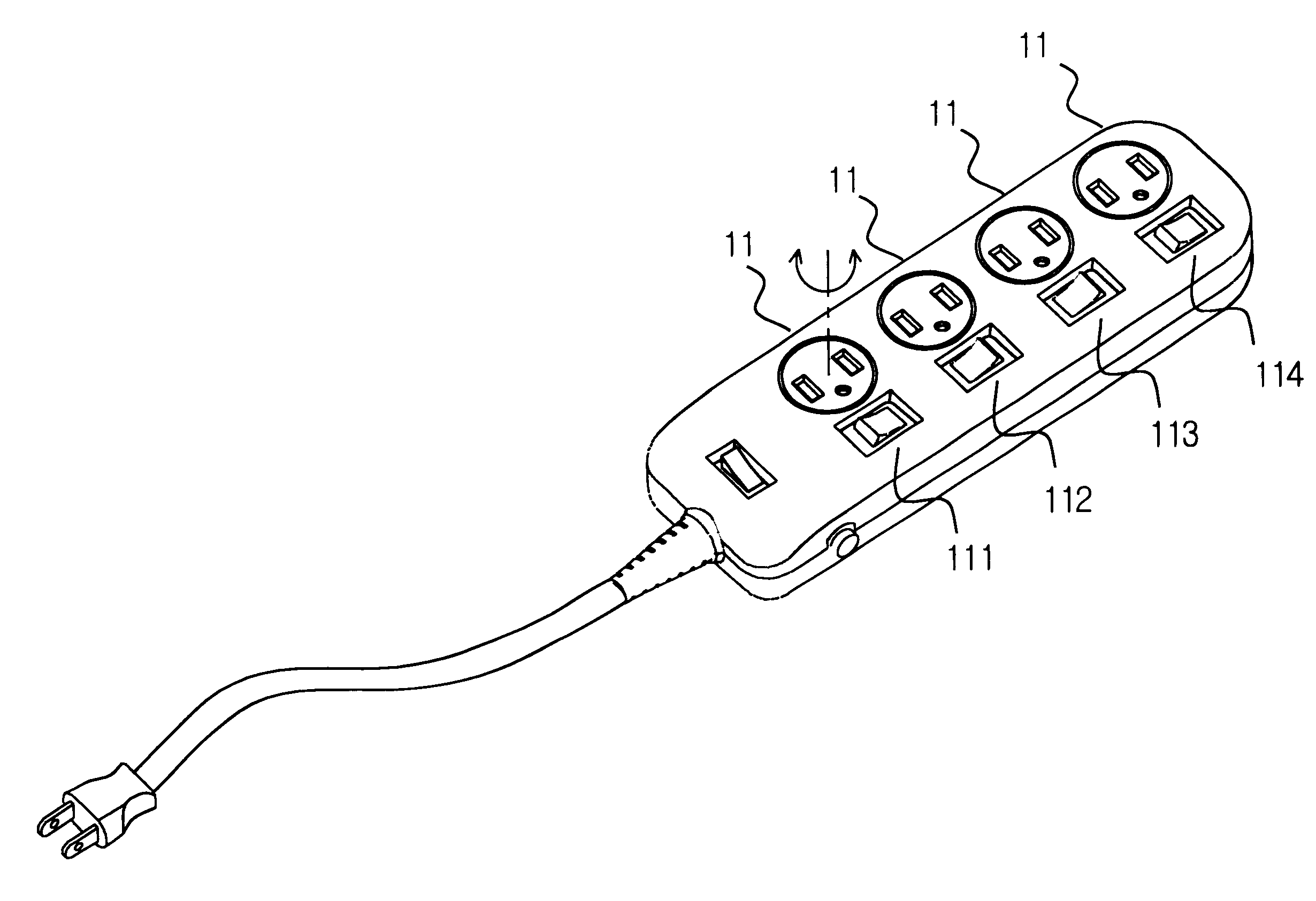
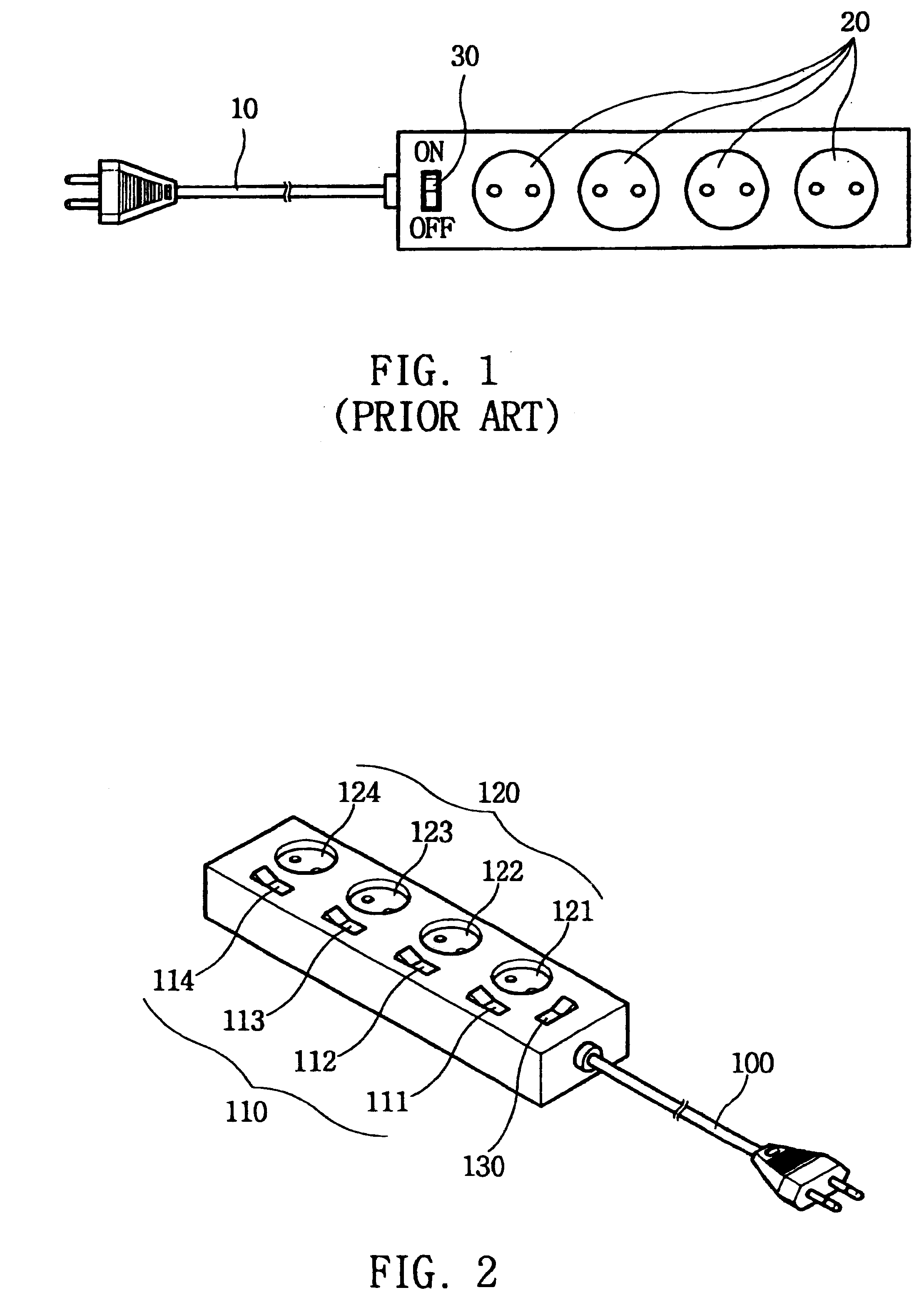
the present invention as shown in FIGS. 2 and 3 will be explained as follows. FIG. 2 is a schematic view illustrating an outer feature of the first embodiment of the present invention. A switch unit 110 comprised of a plurality of individual switches 111.about.114 is installed to a corresponding receptacle 121.about.124 of the receptacle unit 120.

When a plug disposed at the end of the cord 100 is plugged into a wall outlet, the electric power is supplied to a receptacle of the receptacle unit 120 which a corresponded switch of the switch unit 110 is turned on.

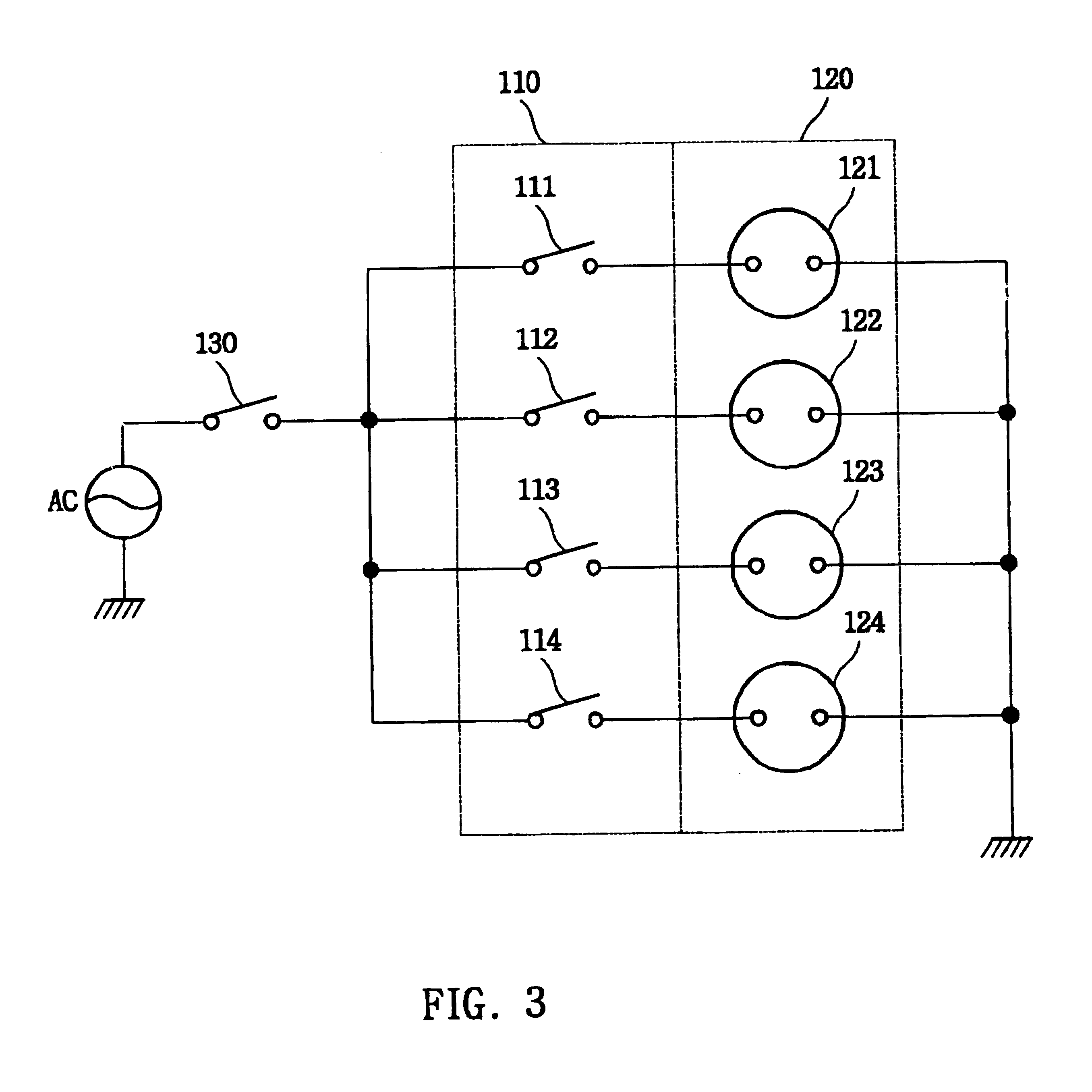
As shown in FIG. 3, one end of switch terminals 111, 112,113114 of the switch unit 110 is connected in parallel to AC power. The other switch terminals 111, 112, 113114 is connected to the receptacles 121, 122, 123124 of the receptacle unit 120 in series, and the other end of the receptacles 121, 122, 123124 is grounded (negative terminal).

When a user turns on a switch 111 of the switch unit 110, the electric power is independe...

second embodiment

the present invention will be explained with reference to FIG. 4 and FIG. 5. FIG. 4 is a schematic drawing illustrating the power-control apparatus. As shown in the drawing, a switch box 210 is integrally formed a plurality of individual switches 221.about.225 in a switch unit 220 for separately supplying the power from the power source to a remote plug unit 260. Remote plug unit 260 is formed by a plurality of individual remote plugs 261.about.266 which each connect to extension cord 250. A main switch 230 is provided between the power supply cord 200 and the individual switches 221.about.225 of the switch unit 220. A timer 240 for setting operation time is connected to a remote plug 266 separately from switch unit 220.

Main switch 230 of switch box 210 allows individual control of switches 221.about.225 and of remote plug unit 260.

The switches described above are paired with the remote plugs. Main switch 230 and switch unit 220 are formed by a bi-polar switch capable of connecting ...

third embodiment

FIG. 6 illustrates the present invention. In this embodiment of the present invention, the power control apparatus includes a plurality of switches 300 for connecting or disconnecting the power to receptacle 320. Switches 300 are separated from each other by a barrier formed between the neighboring switches.

As shown in FIG. 6, a number of switches 300 are installed along the side of one edge at a lower surface than the top surface of housing H where receptacles 320 are located. Each switch 300 is separately installed in a compartment of housing H with a common lid 330. It is possible that this feature will prevent accidental operation of the switch by the turning on or off of a wrong switch. Because barrier wall 310, consisting of a compartment and lid, covers each switch 300 individually, it is possible to prevent erroneous operation of switch 300. For example, a user may step on or press down the switch unintentionally by his body or drop an object on the switch accidentally, thus...


PUM

PropertyMeasurementUnit
rotationaaaaaaaaaa
electrical hazardaaaaaaaaaa
outer diameteraaaaaaaaaa

Abstract

An electric outlet with a plurality of individual switches and rotatable receptacles is provided for efficiently protecting against possible electric hazard and organizing electric extension cords. The electric outlet provides three kinds of rotatable receptacles rotating on a plan plane, vertical plane or both plan and vertical plane simultaneously. The electric outlet rotating simultaneously on a plan and vertical plane comprises a disk-type receptacle and a cylindrical-type receptacle. The disk-type receptacle comprises a top disk part, lower cylindrical body part and a pair of outer stoppers. The cylindrical type receptacle comprises a hollow part for inserting a disk type receptacle, an annular rim, a pair of inner stoppers and shafts. A protecting cover as a safety device installs on top of disk part for automatically blocking the slots. The assembled disk-type and cylindrical-type receptacle is installed to the rotatable electrical outlets. The various decorative electric outlets are also provided to apply thereof.

Description

1. Field of the InventionThe present invention relates to an electrical outlet with rotatable receptacles and individual switches. More particularly, each receptacle is capable of rotating either on a top surface, top to lateral surface or both in order to reduce potential electrical hazards while at the same time organizing electrical cords around the users' area. The various decorative electrical outlets being able to hang on a wall are also provided to apply thereof.2. Description of Related ArtGenerally, a power outlet installed on the wall of a house is used to plug in household electric appliances, electronic devices or personal computers. Since most standard wall-type power outlets provide one or two receptacles in one place, only one or two electronic devices can be plugged in at one place.Often, the number of appliances or electronic devices one needs to plug in exceeds the number of receptacles on the wall-type electric outlet or the wall outlet is located far from the ele...

Claims


Application Information

Patent Timeline
Patent Type & Authority Patents(United States)
IPC IPC(8): C08J9/00H01R25/00H01H9/20H01H9/28H01R35/00H01R13/44H01R13/453H01R13/447H01R35/04H01R13/70
CPCC08J9/0004H01R25/003C08J2300/14H01H9/287H01R13/447H01R13/4534H01R13/70H01R35/00H01R35/04
Inventor LEE, JAE HA
Owner LEE JAE HA
Why Eureka
Try Eureka