Connector assembly

a technology of connecting parts and connectors, applied in the direction of coupling contact parts, coupling device connections, coupling contact parts, etc., can solve problems such as electrical conductivity worsening, and achieve the effect of reducing the worsening of electrical conductivity

Active Publication Date: 2020-04-09
MOLEX INC
View PDF15 Cites 2 Cited by
  • Summary
  • Abstract
  • Description
  • Claims
  • Application Information

AI Technical Summary

Benefits of technology

[0007]An objective of the present disclosure is to propose a connector assembly that prevents insertion of a receptacle terminal at an incorrect orientation, and moreover, reduces worsening of electrical conductivity.

Problems solved by technology

When manufacturing a receptacle connector, there are cases where a worker inserts a receptacle terminal into the housing terminal retention hole incorrectly with the receptacle terminal upside down.
Incorrect orientation of the receptacle terminal could cause non-conformances such as the receptacle terminal not reaching the appropriate position in the terminal retention hole.
However, depending on the structure for preventing insertion of a receptacle terminal at incorrect orientation, the plug terminal may become thin, leading to worsening of electrical conductivity.

Method used


Image

  • Connector assembly
  • Connector assembly
  • Connector assembly

Examples


Embodiment Construction

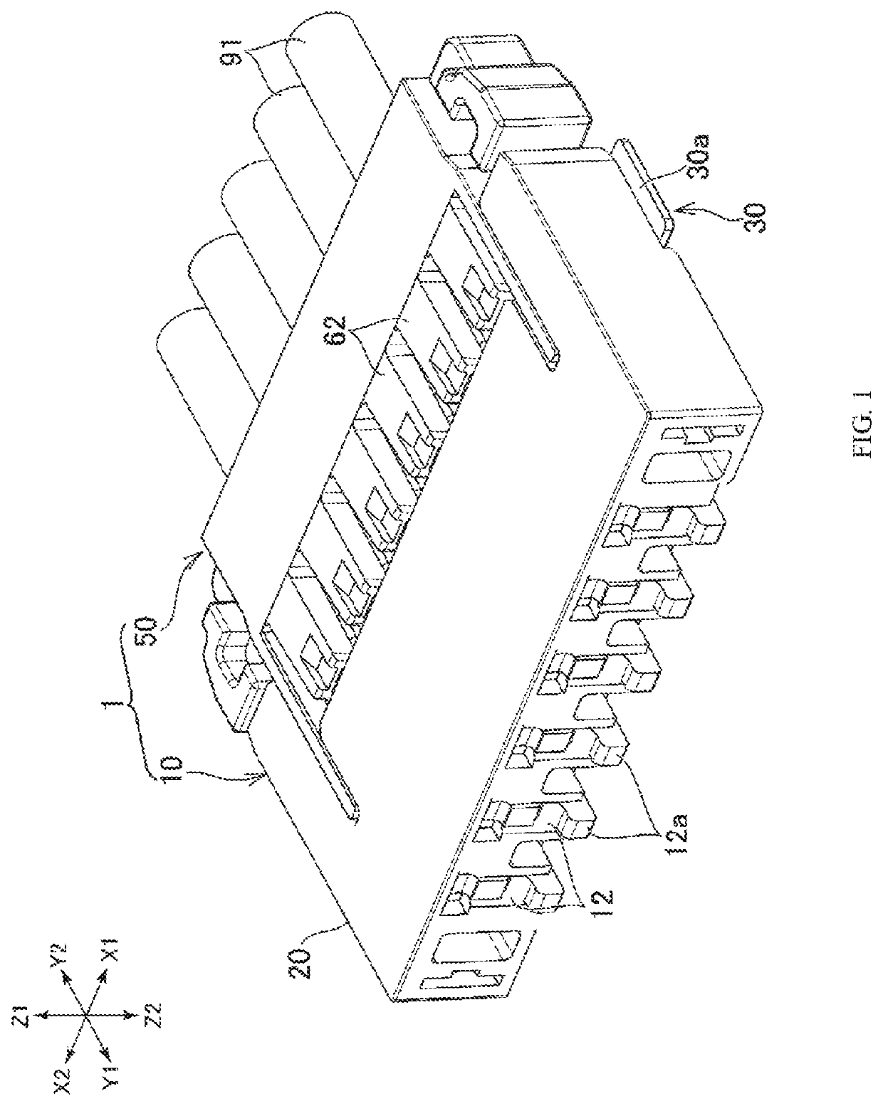
[0023]The connector assembly proposed in the present disclosure is described below. The present specification describes the connector assembly 1 shown in FIG. 1 and the like as an example of a connector assembly. In the following description, the directions indicated by X1 and X2 of FIG. 1 are respectively referred to as the right and the left, while the directions indicated by Y1 and Y2 of FIG. 1 are respectively referred to as forward and backward. Moreover, the directions indicated by Z1 and Z2 are respectively referred to as up and down. While these directions are used to describe the relative positional relationships of parts, members, and sections that make up a connector assembly, they do not limit the orientation of the connector assembly 1 during use.

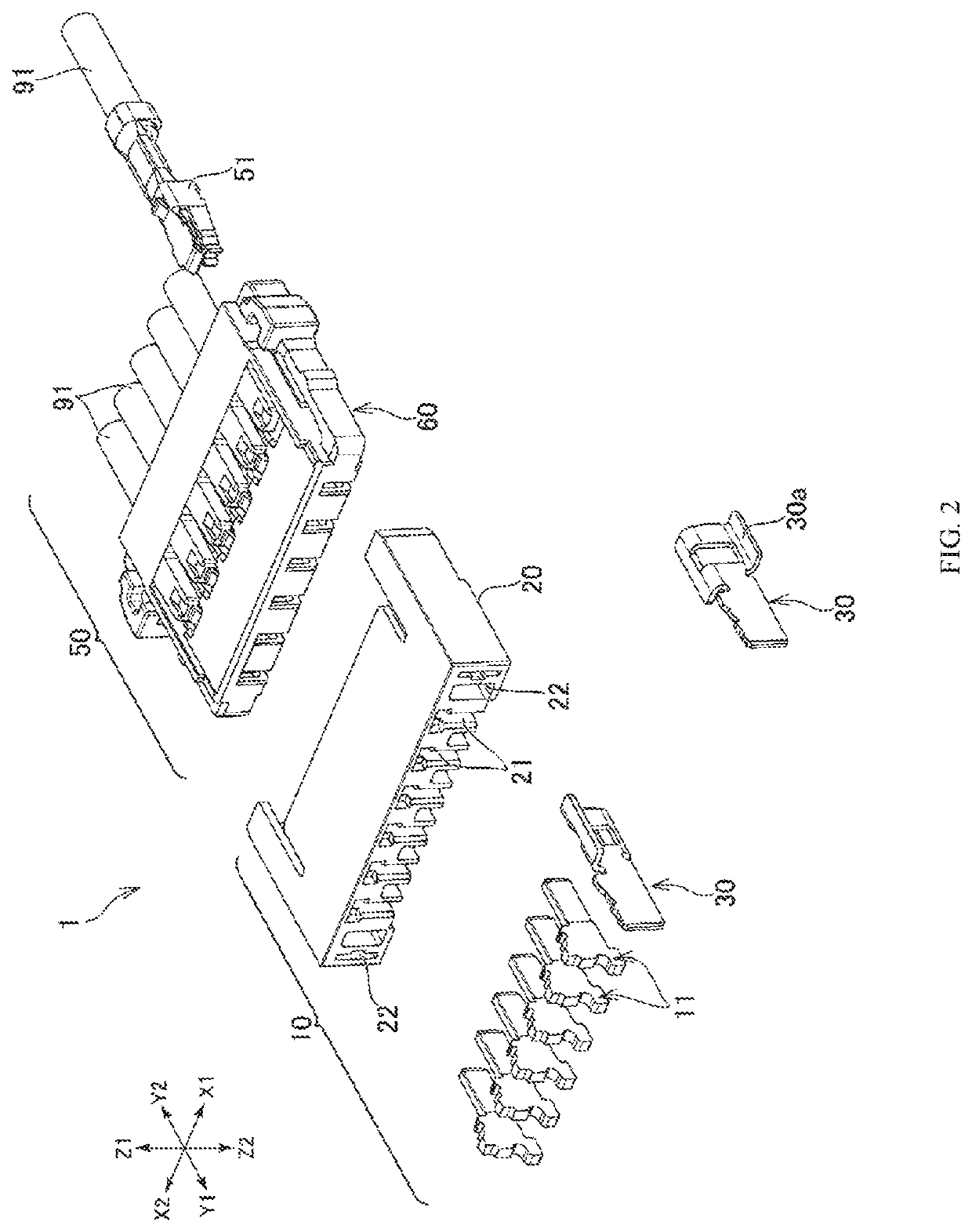
[0024]As shown in FIG. 2, the connector assembly 1 has a plug connector 10 and a receptacle connector 50. In the description of the present specification, the two connectors 10 and 50 can be engaged in the forward and backward ...


PUM


Abstract

A terminal retention hole of a receptacle housing has guide grooves for permitting sliding of protruding guide parts of a receptacle terminal in the engaging longitudinal direction of the protruding guide parts. Each of the plug terminals has a base part and a contact part extending from the base part. A thickness of the plug terminal contact part in the horizontal direction is smaller than the thickness of the plug terminal base part in the horizontal direction.

Description

RELATED APPLICATIONS[0001]This application claims priority to Japanese Application No. 2018-190430, filed on Oct. 5, 2018, which application is incorporated herein by reference in its entirety.TECHNICAL FIELD[0002]The present disclosure relates to a connector assembly.BACKGROUND ART[0003]As exemplified in patent document 1 described below, connectors have been used to date to connected a plurality of cables on a circuit board. One of the connectors has terminals provided on each of the ends of a plurality of cables lined up in the horizontal direction (this connector is called a “receptacle connector” and these terminals are called “receptacle terminals”). Each of the receptacle terminals has a pair of opposing contact parts formed in a plate spring shape. The other end of the connector includes a plurality of terminals soldered to the circuit board (here, this connector is called a “plug connector” and this terminal is called a “plug terminal”) A plug terminal is inserted between a...

Claims


Application Information

Patent Timeline
Patent Type & Authority Applications(United States)
IPC IPC(8): H01R12/58
CPCH01R12/58H01R13/40H01R13/02H01R13/631H01R12/75H01R12/57H01R13/4223H01R13/113H01R13/04H01R13/629H01R13/6273
Inventor ARAI, MASAYUKIAKIYAMA, SHIGERUHE, QIUCEN
Owner MOLEX INC
Why Eureka
Try Eureka