Imaging lens

a technology of imaging lens and lens body, applied in the field of imaging lens, can solve the problems of field curvature generation, and achieve the effect of reducing the focal length of the lens, miniaturizing the imaging lens, and keeping the focal length long

Active Publication Date: 2011-10-13
KANTATSU CO LTD
View PDF1 Cites 42 Cited by
  • Summary
  • Abstract
  • Description
  • Claims
  • Application Information

AI Technical Summary

Benefits of technology

[0011]According to the invention, the first lens is shaped to form a biconvex lens. Therefore, it is possible to set the refractive power of the first lens relatively strong, so that it is possible to suitably attain miniaturization of an imaging lens. On the other hand, with this first lens having positive refractive power, there remains a concern of generation of field curvature. For this reason, according to the invention, disposing on the image side of the first lens the second lens having negative refractive power so as to direct the concave surface on the object side, it is possible to reduce worsening of the field curvature generated at the first lens. Therefore, according to the imaging lens of this invention, despite the small size, it is possible to satisfactorily correct the aberrations.
[0016]When the above conditional expression (2) is satisfied, it is possible to keep the axial chromatic aberration and spherical aberration stable. When the value exceeds the upper limit “0.6”, since the refractive power of the second lens increases, the axial chromatic aberration is in the plus direction in relative to that of a reference wavelength and is excessively corrected. In addition, the spherical aberration is in the plus direction at a ring zone section and is excessively corrected.
[0024]When the aforementioned conditional expression (4) is satisfied, it is possible to keep the maximum angle of emergence of the off-axis principal light beam small while keeping each aberration stable. When the value exceeds the upper limit “1.0”, since the refractive power of the fourth lens decreases, while it is easy to correct the coma aberration and the chromatic aberration of magnification, the maximum angle of emergence of the off-axis principal light beam becomes large and a shading phenomenon more easily occurs. On the other hand, when the value is below the lower limit “0.4”, since the refractive power of the fourth lens increases, although it is possible to reduce the maximum angle of emergence of the off-axis principal light beam, it is difficult to correct the field curvature and the distortion.
[0028]When the imaging lens has a configuration that satisfies the conditional expression (6), a position of a principal point of the optical system moves towards the object side, so that it is possible to attain miniaturization of an imaging lens while keeping the focal length long. Here, it is effective to satisfy the conditional expression (5) also as a means to supplement insufficient correction of axial chromatic aberration.
[0029]According to the imaging lens of the invention, it is possible to both reduce the size of the imaging lens and correct the aberration properly, thereby making it possible to provide the imaging lens with the small size capable of correcting aberrations properly.

Problems solved by technology

On the other hand, with this first lens having positive refractive power, there remains a concern of generation of field curvature.

Method used


Image

  • Imaging lens
  • Imaging lens
  • Imaging lens

Examples


first embodiment

[0045]Hereunder, referring to the accompanying drawings, a first embodiment of the present invention will be fully described.

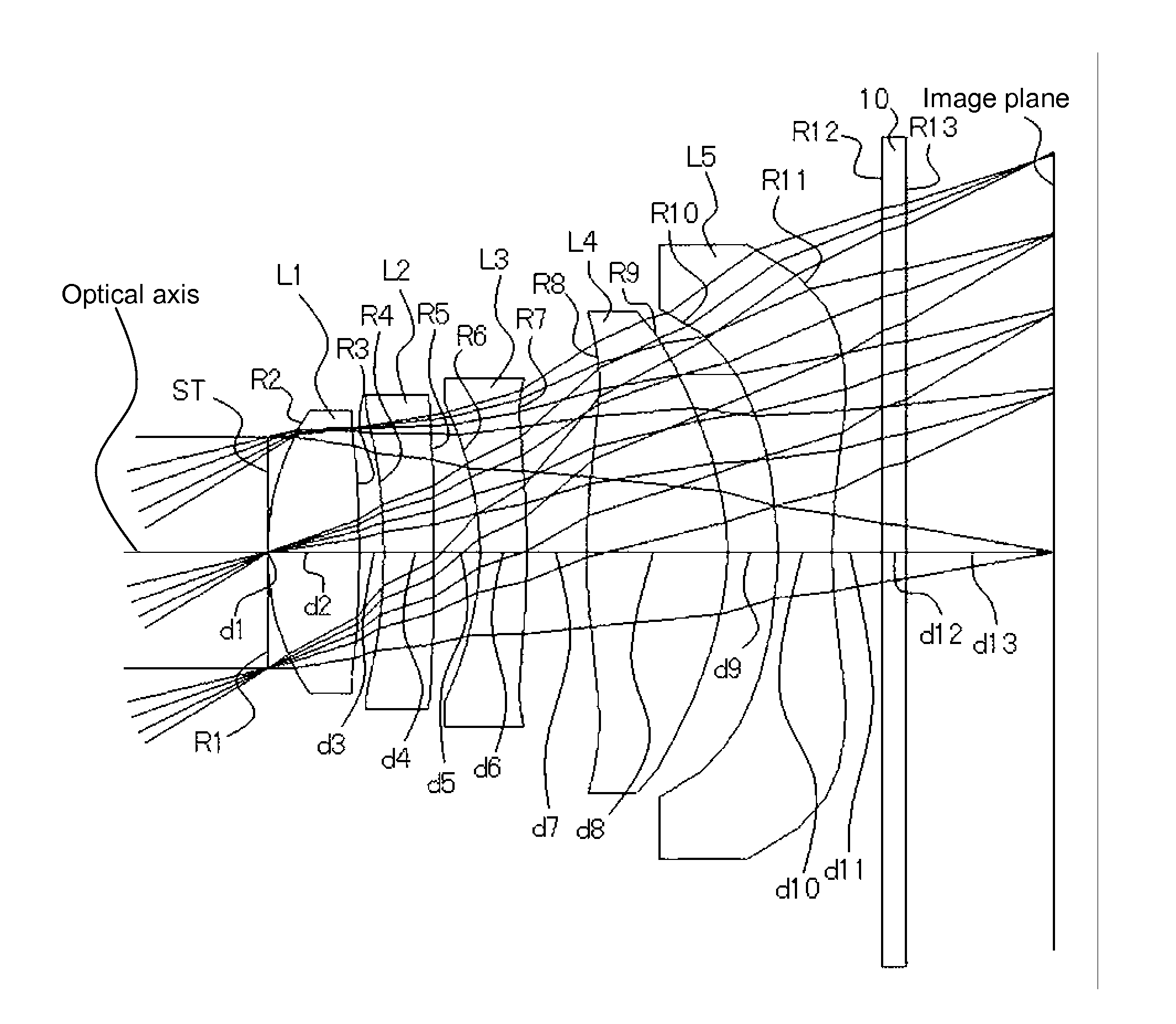
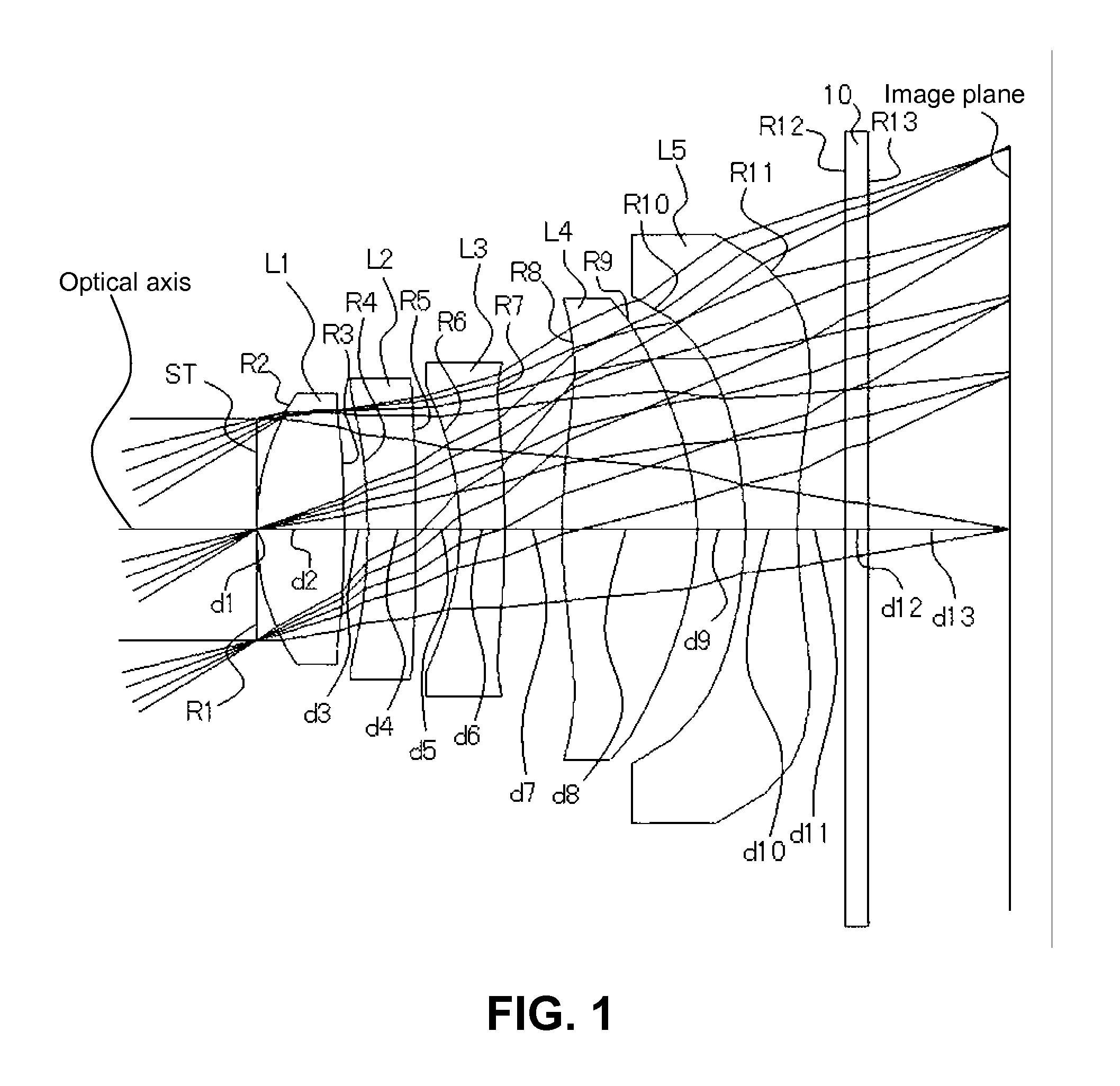
[0046]FIGS. 1, 4, and 7, and 10 are schematic sectional views showing image lenses in Numerical Data Examples 1 to 4 according to the embodiment, respectively. Since a basic lens configuration is the same among the Numerical Data Examples 1 to 4, the lens configuration of the embodiments will be described with reference to the lens sectional view of Numerical Data Example 1.

[0047]As shown in FIG. 1, the imaging lens of the embodiment includes an aperture stop ST; a first lens L1 having positive refractive power; a second lens L2 having negative refractive power; a third lens L3 having negative refractive power; a fourth lens L4 having positive refractive power; and a fifth lens L5 having negative refractive power, which are arranged in this order from an object side to an image side of the imaging lens. A cover glass 10 is provided between the fifth lens L5 an...

second embodiment

[0068]Hereunder, referring to the accompanying drawings, a second embodiment of the invention will be described. Similarly to the imaging lens of the first embodiment, the imaging lens of this embodiment includes an aperture stop ST; a first lens L1 having positive refractive power; a second lens L2 having negative refractive power; a third lens L3 having negative refractive power; a fourth lens L4 having positive refractive power; and a fifth lens L5 having negative refractive power, which are arranged in this order from the object side towards the image side of an imaging lens. A cover glass 10 is provided between the fifth lens L5 and the image plane.

[0069]According to the imaging lens of this embodiment, however, the second lens L2 is a biconcave lens, the first lens L1 and the second lens L2 are combined as shown in FIG. 13. With the lens configuration like this, it is possible to more suitably correct chromatic aberration.

[0070]More specifically, in the imaging lens of this em...


PUM


Abstract

An imaging lens includes an aperture stop, a positive first lens with a biconvex shape, a negative second lens; a negative third lens, a positive fourth lens, and a negative fifth lens arranged in this order from an object side. When the whole lens system has a focal length f, focal lengths and Abbe's numbers of the first and the second lenses are f1, νd1, f2, and νd2, focal lengths of the fourth and fifth lenses are f4 and f5, a composite focal length of the first lens L1 and the second lens L2 is f12, and a distance from a surface of the first lens L1 on the object side to a surface of the fifth lens L5 on the image side is Σd, the imaging lens satisfies the following conditional expressions:0.7<f12 / f<1.40.2<|f1 / f2|<0.615<νd1−νd20.4<f4 / f<1.0Σd / f<1.2|f5 / f|<1.0

Description

CROSS-REFERENCE TO RELATED APPLICATIONS[0001]This is a continuation application of the prior PCT application PCT / JP2009 / 006799, filed on Dec. 11, 2009, pending, which claims priority from a Japanese patent application No. 2008-329285, filed on Dec. 25, 2008, the entire content of which is incorporated herein by reference.BACKGROUND OF THE INVENTION AND RELATED ART STATEMENT[0002]The present invention relates to an imaging lens for forming an image on an imaging element such as a CCD sensor and a CMOS sensor. In particular, the present invention relates to an imaging lens suitable for mounting in a relatively small camera such as a cellular phone, a digital still camera, a portable information terminal, a security camera, an onboard camera, and a network camera.[0003]An imaging lens to be mounted in a small camera has been required to have a high resolution lens configuration suitable for a recently developed imaging element with a high resolution, as well as to use a fewer number of...

Claims


Application Information

Patent Timeline
Patent Type & Authority Applications(United States)
IPC IPC(8): G02B9/60
CPCG02B13/0045G02B9/60
Inventor KUBOTA, YOJI
Owner KANTATSU CO LTD
Why Eureka
Try Eureka