High-capacity juicing machine

a juicing machine, high-capacity technology, applied in the field of high-capacity juicing machines, can solve the problems of deformation of the first juicing member b>151/b>, and achieve the effect of improving juicing performance, simple structure and easy manufacturing

Inactive Publication Date: 2020-04-16
LEE MUN HYUN
View PDF0 Cites 1 Cited by
  • Summary
  • Abstract
  • Description
  • Claims
  • Application Information

AI Technical Summary

Benefits of technology

[0037]According to the present invention, the high-capacity juicing machine has the simple structure which is easily manufactured, and improves the juicing performance.

Problems solved by technology

However, there is a problem in that since the thickness of the first juicing member 151 is limited, if the pressure is increased, the first juicing member 151 is deformed.

Method used


Image

  • High-capacity juicing machine
  • High-capacity juicing machine
  • High-capacity juicing machine

Examples


Embodiment Construction

[0052]Hereinafter, a high-capacity juicing machine according to preferred embodiments of the present invention will be described in detail with reference to the accompanying drawings.

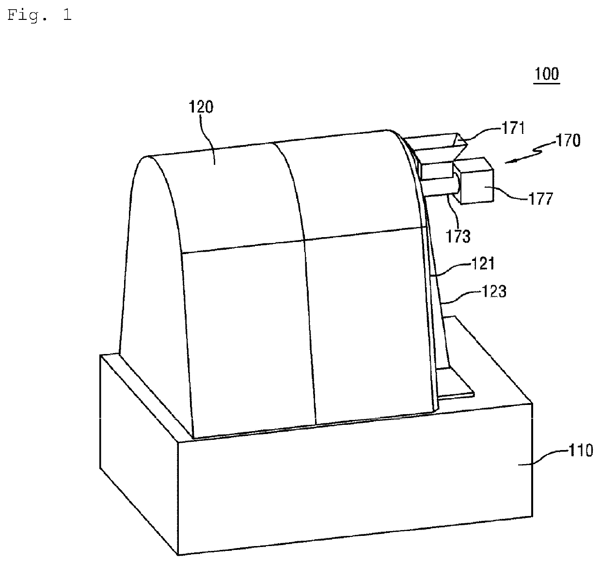
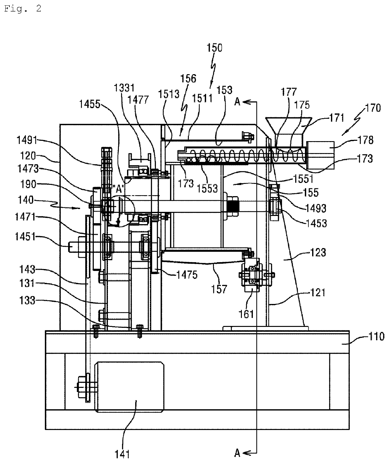
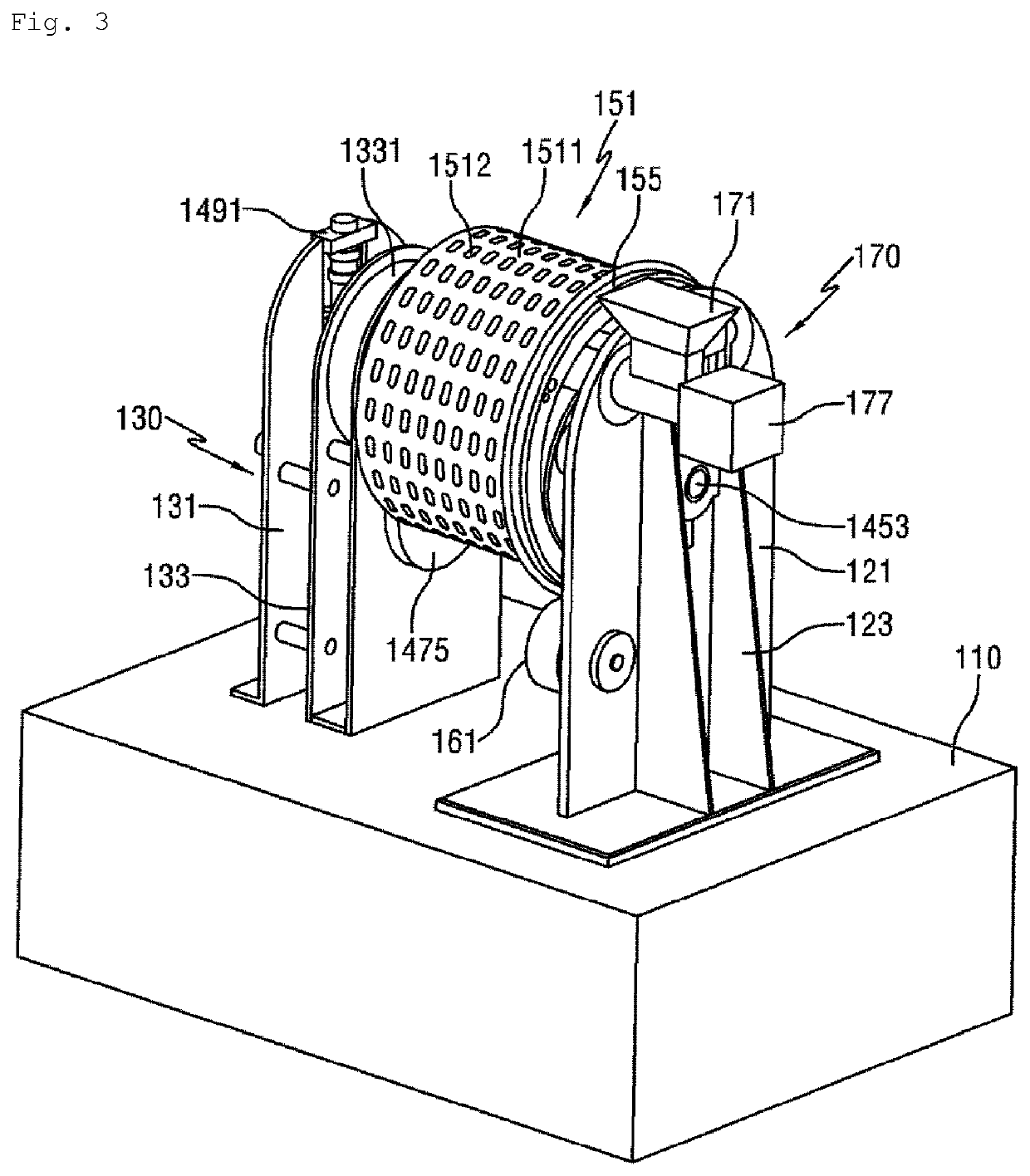
[0053]FIG. 9 is a side view schematically illustrating a high-capacity juicing machine according to one embodiment of the present invention. FIG. 10 is a perspective view schematically illustrating a part of a juicing member of the high-capacity juicing machine according to one embodiment of the present invention. FIG. 11 is a cross-sectional view illustrating a first juicing member of the high-capacity juicing machine according to one embodiment of the present invention, in which the circle is an enlarged cross-sectional view illustrating a part of the first juicing member. FIG. 12 is a view schematically illustrating a positional relationship between juicing members of the high-capacity juicing machine according to one embodiment of the present invention. FIG. 13 is a cross-sectional view illustrating...


PUM


Abstract

A high-capacity juicing machine includes: a base (210); a first support (230) and a second support (250) which are provided on the base (210) and are spaced from each other in a longitudinal direction; a first juicing member (270) having a first support shaft (275) rotatably provided on the first support (230) and an outer hollow rotor (271) which is positioned between the first support (230) and the second support (250); a second juicing member (290) having a second support shaft (293) rotatably provided on the second support (250), and an inner rotor (291) which is eccentrically positioned inside the first juicing member (270), and which is coupled to the second support shaft (293) to rotate together with the second support shaft; a first driving member (240) for driving the first support shaft (275); and a second driving member (260) for driving the second support shaft (293).

Description

TECHNICAL FIELD[0001]The present invention relates to a high-capacity juicing machine having a simple structure to improve juicing performance.BACKGROUND ART[0002]In general, a juicing machine is a kind of extractor that compresses and extracts materials (hereinafter referred to as a juiced material), such as various vegetables or fruits.[0003]As illustrated in FIGS. 1 to 8, a juicing machine according to the related art includes a base 110 serving as a support, a support unit 130 fixed to the base 110, a juicing unit 150 rotatably provided to the support unit 130, an introducing unit 170 for supplying the juiced material to the juicing unit 150, a discharge unit 180 for discharging residues from the juicing unit 150, and a driving unit 140 for rotating the juicing unit 150. Parts of the above components are housed by a housing 120.[0004]As illustrated in FIGS. 2 and 5, the juicing unit 150 has a first juicing member 151 and a second juicing member 155 positioned inside the first ju...

Claims


Application Information

Patent Timeline
Patent Type & Authority Applications(United States)
IPC IPC(8): A47J19/02A23N1/00
CPCA47J19/025A23N1/00B30B9/207A23N1/02A47J19/06A47J31/4403
Inventor LEE, MUN HYUN
Owner LEE MUN HYUN
Why Eureka
Try Eureka