Tire Pressure Equalization and Inflator

US20200148391A1Active Publication Date: 2020-05-14THREE ZERO RIGHT LLC
0 Cites 0 Cited by

Patent Information

Authority / Receiving Office
US · United States
Current Assignee / Owner
Publication Date
2020-05-14

Smart Images

  • Figure 1
    Figure 1
  • Figure 2
    Figure 2
  • Figure 3
    Figure 3
Patent Text Reader

Abstract

An apparatus and method to equalize the pressure in multiple tires supported by a single axle or strut of an airplane is shown. A control block connects the pressurized gas to a distribution block and meter. From the distribution block high pressure lines and no-loss chuck valves connect the pressurized gas to the multiple tires. Steps to be followed as programmed in the meter include startup, testing, calibration, setup and finalize. A permanent record of the steps in equalizing tire pressures is maintained.
Need to check novelty before this filing date? Find Prior Art

Description

BACKGROUND OF THE INVENTION1. Field of the Invention

[0001] The invention generally relates to the inflation and maintaining equal pressure between dual tires and, more particularly, the apparatus and method used in the equalization and / or inflation.2. Description of the Prior Art

[0002] When a single tire does not have enough strength to support a load, a common way to solve the problem is to add additional tires. In aircraft, this is accomplished by either having more than one tire on an axle, or adding additional axles with additional tires, all of which are suspended from a single strut. Depending on the design of the aircraft, additional struts with additional tires may be added.

[0003] In an aircraft it is extremely important for all the tires connected to a single strut to have equal pressure. The strut may have dual tires on a single axle on which the pressure needs to be equalized. In bigger systems, a single strut may support multiple axles with tires being on each end of each a...

Examples

Embodiment Construction

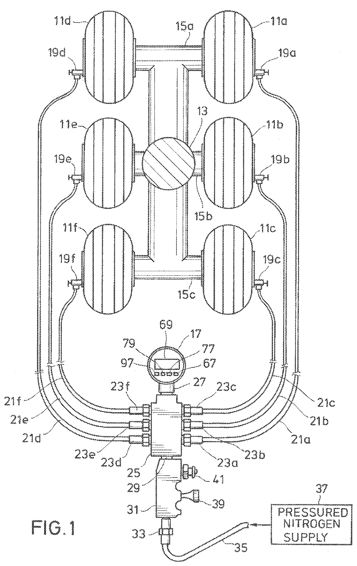
[0022]Assume an aircraft has landed that has six wheels 11a, 11b, 11c, 11d, 11e and 11f attached to a single strut 13 connecting axles 15a, b, and c (see FIG. 1). After some preliminary diagnostic work by the meter 17, as will be described subsequently, no loss chuck valves 19a, 19b, 19c, 19d, 19e and 19f are connected to the valve stems of wheels 11a, 11b, 11c, 11d, 11e and 11f, respectively. The no loss chuck valves 19a thru 19f connect through high pressure nitrogen lines 21a, 21b, 21c, 21d, 21e and 21f, respectively, to high pressure fittings 23a, 23b, 23c, 23d, 23e and 23f, respectively. The high pressure fittings 23a through 23f connect to the nitrogen distribution block 25.

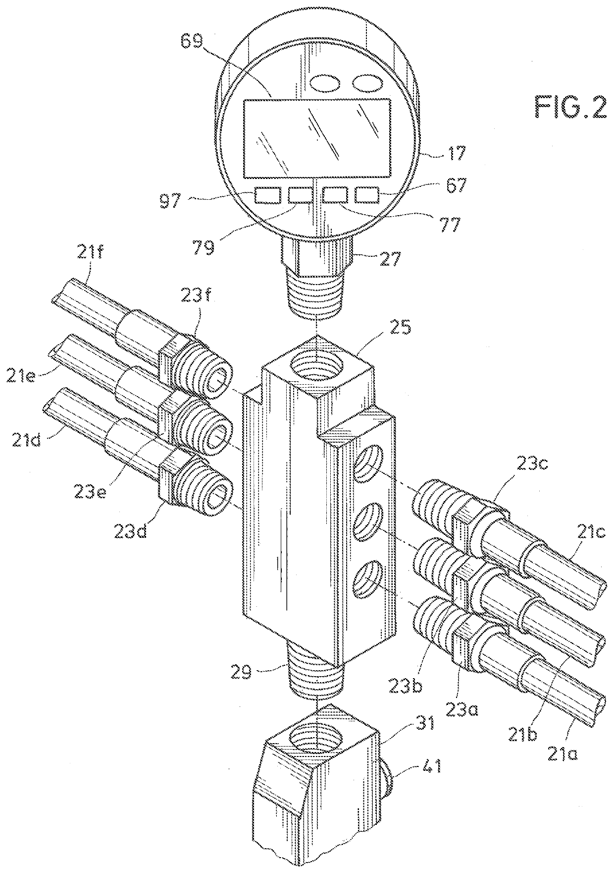
[0023]Referring to FIG. 2 in combination with. FIG. 1, the connections to the nitrogen distribution block 25 by each of the fittings 23a thru 23f is shown in more detail. The meter 17 is connected to the nitrogen distribution block 25 by meter fitting 27. The bottom of the nitrogen distribution block 25 is ...