System and method for assembling a package with a flip-top

a technology of self-latching and packaging, applied in the field of automatic packaging machines, can solve the problems of increasing unbalanced mandrels used in the conventional assembly device, and adding a significant amount of complexity to any machine for assembling and filling packages, etc., to achieve the effect of reducing complexity and assembly time, high efficiency, and reducing labor intensity

Inactive Publication Date: 2005-02-03
BW INTEGRATED SYST LLC
View PDF28 Cites 1 Cited by
  • Summary
  • Abstract
  • Description
  • Claims
  • Application Information

AI Technical Summary

Benefits of technology

[0013] It is still another object of the invention to provide a system and method for assembling a “flip-top” package that can be assembled in a minimal amount of time.
[0014] In accordance with the invention and the above examples of objects, a system and method is provided for assembling a “partial flip-top” box or package in a highly efficient manner. In a preferred embodiment, a plurality of mandrels are coupled to an “endless link” chain conveyor. Each mandrel includes a mounting bracket for coupling the mandrel to a rail. The bracket is operatively connected to a package-holding subassembly. The package-holding assembly includes a gripping mechanism for holding the package blank during assembly. The package-holding assembly is rotatable about a first axis relative to the rest of the mandrel. A flap holder subassembly is also operatively connected to the bracket. The flap holder assembly is rotatable about a second axis substantially perpendicular to the first axis. The rotation of the package-holding assembly permits the package blank to be moved into various orientations such that the blank can be quickly and efficiently assembled into a “partial flip-top” package. In one preferred embodiment of the invention, the system and method results in up to 400 partial flip-top packages being assembled per minute.

Problems solved by technology

This new type of “partial flip-top” package requires several more distinct flaps than the previous packages, which adds a significant amount of complexity to any machine for assembling and filling the packages.
In particular, problems arise because the mandrels used in the conventional assembly devices are not properly aligned to fold down the top panels of the package blank to form the flip-top of the package.
This results in increased complexity and assembly time, diminishing the assembly machine's efficiency.

Method used


Image

  • System and method for assembling a package with a flip-top
  • System and method for assembling a package with a flip-top
  • System and method for assembling a package with a flip-top

Examples


Embodiment Construction

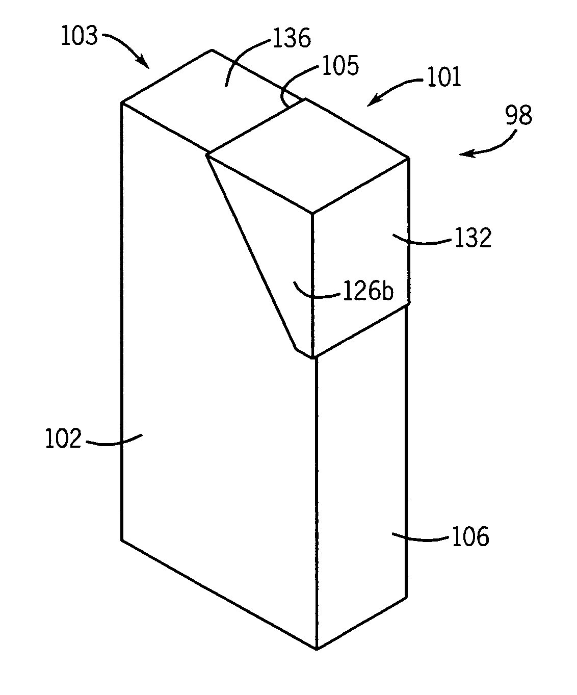
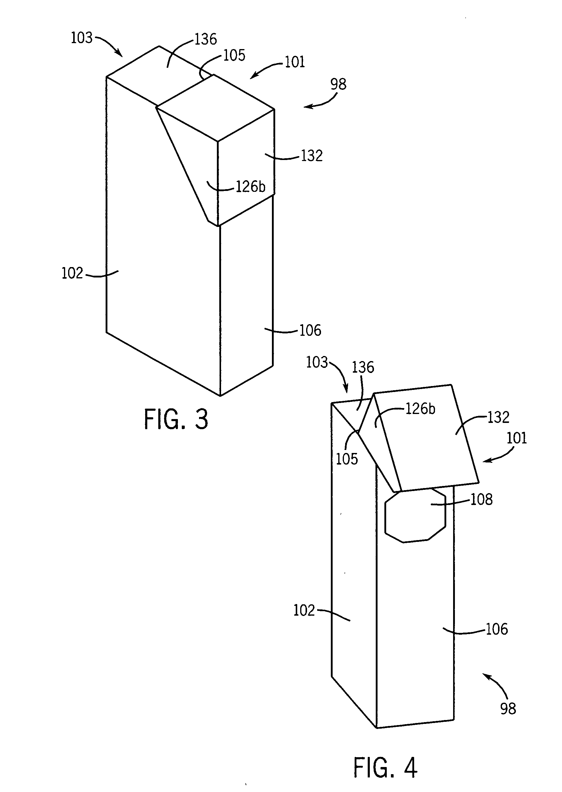
[0033]FIGS. 3 and 4 show a paperboard package 98 including a “partial” latching flip-top package flip-top 101 which is folded, formed, filled, and sealed by an automatic package machine according to one form of the invention. The package 98, has the flip-top 101 hingedly connected to an upper portion 103 of the package 98. The hinge 105 between the flip-top 101 and the upper portion 103 runs along the (shorter) minor plane of the package, substantially perpendicular to where the hinge line would be on a conventional “flip top” package. The hinge 105 runs across the middle of the upper portion 103. The package 98 includes a hole 108 within a minor side panel 106 of the package 98 instead of having the top entirely open when the flip-top 101 is “flipped open.” In this new package, the hole 108 is exposed when the flip-top 101 is flipped open, as shown in FIG. 4, and the hole 108 is unexposed when the flip-top 101 is closed.

[0034]FIG. 5 shows a paperboard package blank 99 that is ulti...


PUM


Abstract

An automatic packaging machine for forming a latching flip-top box from a blank. A plurality of mandrels are coupled to a conveyor system. Each of the mandrels include a mounting block for coupling the mandrel to the automatic packaging machine, a package-holding assembly operatively connected to the mounting block and being rotatable about a first axis from a first position to a second position, and a flap holder assembly operatively connected to the mounting block. The flap holder assembly is rotatable about a second axis substantially perpendicular to the first axis. A plurality of plows and tucker assemblies sequentially manipulate portions of the blank in order to form portions of the box.

Description

FIELD OF THE INVENTION [0001] The present invention relates generally to automatic packaging machines. More particularly, the present invention relates systems and method for assembling self-latching boxes and / or packages with a flip top. BACKGROUND OF THE INVENTION [0002] Various types of automatic packaging machines are known and used for assembling paperboard and / or cardboard packages from precut box blanks. These packages can be used to hold a wide variety of items, ranging from chewing gum to candy to office supplies: U.S. Pat. Nos. 4,578,929; 4,548,593; 4,716,714; 4,829,751; 4,856,566; 4,982,556; 5,010,929; 5,072,573; 5,144,790; and 6,195,959 are examples of packaging machines which may be used to load small items into different types of packages. [0003] Conventional automatic packing machines include a conveyor, usually an endless link chain conveyor, which travels through or past a number of work stations extending between a magazine containing package blanks and a product d...

Claims


Application Information

Patent Timeline
Patent Type & Authority Applications(United States)
IPC IPC(8): B31B5/78B31B50/50B31B50/54B65B25/00B65B43/10B65B43/26B65D5/66B65D5/72
CPCB31B1/54B31B1/78B31B2201/2675B31B2201/281B31B2201/286B31B2201/29Y10S493/911B65B25/005B65B43/10B65B43/265B65D5/6623B65D5/727B31B2203/003B31B50/54B31B50/78B31B2100/00B31B2120/30B31B50/788B31B50/004
Inventor TISMA, PETARKOKOTOVIC, YUGOSLAVBAJIC, RADOJETISMA, STEVAN
Owner BW INTEGRATED SYST LLC
Why Eureka
Try Eureka