Detection device and sample detection method capable of visually reading test results

Active Publication Date: 2020-05-14
LEADWAY HK
View PDF4 Cites 2 Cited by
  • Summary
  • Abstract
  • Description
  • Claims
  • Application Information

AI Technical Summary

Benefits of technology

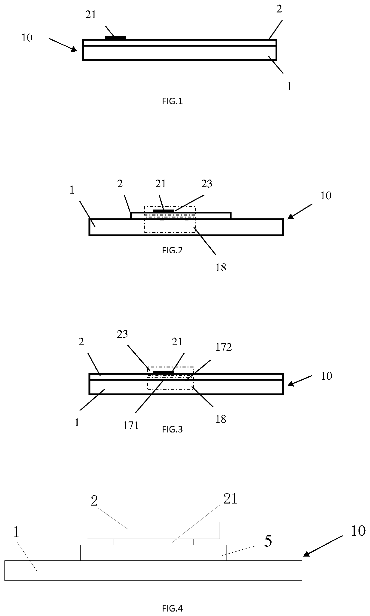
The present invention provides a detection device and a method of manufacturing the detection device that can better detect and display the detection results. The detection device comprises a sample detection layer with a detecting reagent that changes color when it comes into contact with a gas, and a symbol display layer that is treated with an indicator that changes color when it comes into contact with the gas. The device also includes a gas channel between the sample detection layer and the symbol display layer. The symbol display layer is a transparent or translucent material that can observe the detection result of the sample detection layer. The detection device can be used in various applications, such as in the detection of analytes in samples.

Problems solved by technology

However, because the material of the test area also has a certain transparency in the dried situation, the indication line can be seen faintly just before the product detection, which will affect the appearance of the products.
The main problem of this processing manner is that the production process is complex, It needs a lot of steps to assemble and process to make it.

Method used


Image

  • Detection device and sample detection method capable of visually reading test results
  • Detection device and sample detection method capable of visually reading test results
  • Detection device and sample detection method capable of visually reading test results

Examples


embodiment 5

[0135]The device structure of embodiment 5 is the same as that of embodiment 1 or embodiment 3, except that the ammonium salt for generating gas may be separately added to the liquid passage before the detection line, such as the sample pad, the labelled pad, the gas generating pad or the detecting pad.

embodiment 6

[0136]The device structure of the embodiment 6 is the same as that of the embodiment 1 or the embodiment 3. The ammonium salt and the alkaline buffer salt can be separately treated on the sample pad with a certain distance therebetween. That is, ammonium salt and the alkaline buffer salt do not contact before the sample is added to the sample pad, and after the sample flows on the sample pad, one of the ammonium salt and the alkaline buffer salt (the one flows upstream of the sample is treated) is carried to other place, and reacted between both and a gas is generated to change the color of the indicator.

embodiment 7

[0137]The device structure of embodiment 7 is the same as that of embodiment 1, and the ammonium salt and the alkaline buffer salt can be separately treated on the gas generating pad with a certain distance therebetween. That is, the ammonium salt and the alkaline buffer salt do not contact before the sample flows onto the gas generating pad, and when the sample flows onto the gas generating pad, one of the ammonium salt and the alkaline buffer salt (the one flows upstream of the sample is treated) is carried to other place, and reacted between both and a gas is generated to change the color of the indicator.

Embodiment 8: Detection Device of Vertical Flow Described in FIGS. 11 and 12

[0138]In the design embodiment of FIGS. 11 to 12, the detection device 10 is a liquid vertical flow detection structure, comprising a symbol display layer 2 and a sample detection layer 1, the said symbol display layer 2 covers on the sample detection layer 1; wherein, the sample detection layer 1 compri...


PUM


Abstract

A detection device (10), comprising a sample detection layer (1) provided thereon with a detection reagent reacted with an analyte and a result display region (18), wherein the device further comprises a symbol display layer (2) on which an indicator (21) is processed; after the indicator contacts with a gas which can change the color of the indicator, the indicator changes from a first color to a second color. The present invention also relates to a detection cassette (40) comprising the detection device and a sample detection method capable of visually reading detection results achieved by the detection device. The device of the present invention can stabilize and explicitly display the detection results to make common operators obtain the detection results more visually so that the crowd and range of using the detection device are wider

Description

FIELD OF THE INVENTION[0001]The present invention relates to the field of detection, and in particular to a detection device for determining whether an analyte is present in a sample and a method of manufacturing a detection device, and a sample detection method for detecting a sample using the detection device.BACKGROUND OF THE INVENTION[0002]The existing detection device using the lateral flow method generally includes a test strip, a sample pad, a labelled pad, a detecting pad and a sample absorption pad are sequentially mounted on the test strip, and the detecting pad includes a detection line and a control line. The detection line is used to determine whether the analyte is present in the sample. If it is positive, it means that the analyte is present in the sample, and if it is negative, it means that the analyte is not present in the sample. The control line is used to check and confirm the success of this detection. In order to more visually show whether an analyte is presen...

Claims


Application Information

Patent Timeline
IPC IPC(8): G01N21/78
CPCG01N21/78G01N2021/7756G01N33/558G01N33/76G01N21/783G01N21/8483G01N31/221G01N21/80G01N33/54388G01N2470/04G01N2021/7759G01N33/54391
Inventor FEI, FENG QINZHANG, CHUNXIASHANG, TAO
Owner LEADWAY HK
Why Eureka
Try Eureka