PLL status detection circuit and method thereof

Active Publication Date: 2015-10-13
REALTEK SEMICON CORP
View PDF14 Cites 3 Cited by
  • Summary
  • Abstract
  • Description
  • Claims
  • Application Information

AI Technical Summary

Benefits of technology

The patent describes a circuit and method to test the status of a PLL clock in a chip. The test checks if the PLL is in good condition and measures the average jitter of the PLL clock. This helps to determine if the PLL is responsible for any test failures. The detection circuit is not affected by manufacturing process, voltage, or temperature, which provides a relatively stable detection result. The method can also be used for chip functional testing.

Problems solved by technology

In other words, a chip's failure in the at-speed test may result either from a defect of the chip itself or from imperfection of the test clock.
For example, the clock generated by the PLL has a large jitter, or the frequency of the clock is not as expected because settings for the PLL are incorrect, or because a control signal that controls the PLL is subject to the test contents of the at-speed test.
In addition, since the PLL is critical in providing an accurate working clock for the entire chip to work properly, a malfunction in the PLL can lead to unexpected errors.
Although an abnormal operation of the PLL can be detected by the test circuit, the quality of the PLL clock and whether the abnormal operation is caused by false settings of the PLL cannot be known.
In addition, the sampling clock EXT_CLK must be precisely controlled to slightly lead the PLL clock PLL_CLK to accurately sample the PLL clock PLL_CLK; such limitation increases the difficulty in practicing the test.
A shortcoming of this circuit is that the oscillator is so easily affected by manufacturing, voltage and temperature that the oscillating signal becomes unstable.
Whenever there is a change in manufacturing, voltage and / or temperature, the measure result becomes inaccurate.
In short, this circuit is not capable of determining how the temperature affects the PLL because the temperature has a greater influence on the reference clock (i.e., the oscillating signal) than on the PLL clock.

Method used


Image

  • PLL status detection circuit and method thereof
  • PLL status detection circuit and method thereof
  • PLL status detection circuit and method thereof

Examples


Embodiment Construction

[0018]The following description is written by referring to terms of this technical field. If any term is defined in the specification, such term should be explained accordingly. In addition, the connection between objects or events in the following embodiments can be direct or indirect provided that these embodiments are still applicable under such connection. Said “indirect” means that an intermediate object or a physical space exists between the objects, or an intermediate event or a time interval exists between the events. A PLL status detection circuit and method thereof are disclosed, and the detail known in this field is omitted if such detail has little to do with the features of the present disclosure. People of ordinary skill in the art can choose components or steps equivalent to those described in this specification to carry out the present disclosure, which means that the scope of this disclosure is not limited to the embodiments in the specification. On account of that ...


PUM


Abstract

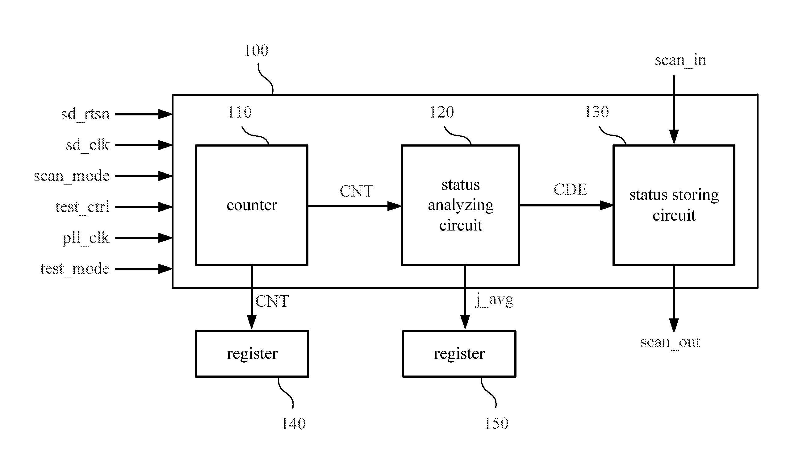
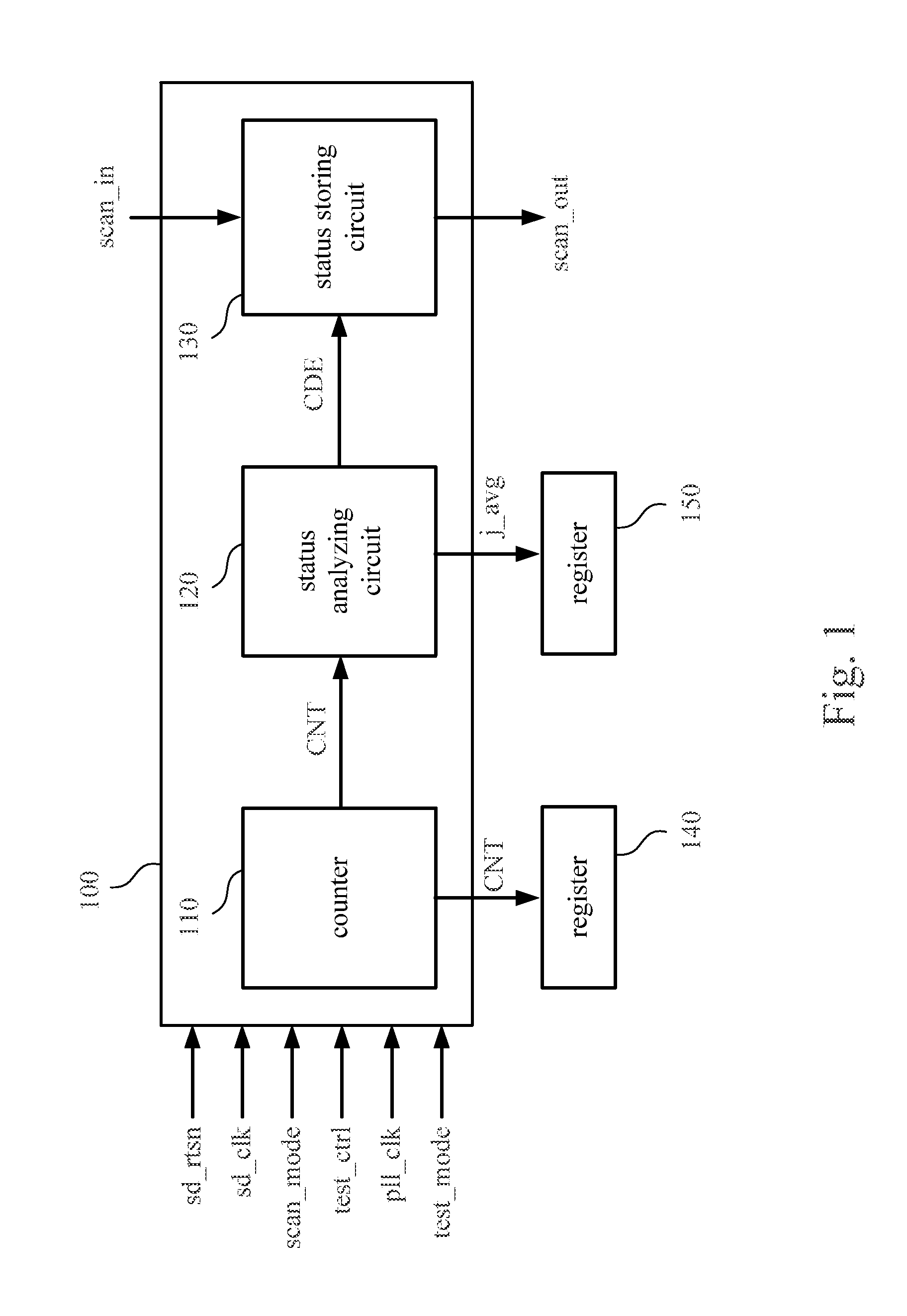
A PLL status detection circuit and its associated method are disclosed herein. The circuit and the method are used to detect a PLL clock generated by a PLL of a chip to determine a status of the PLL. The PLL status detection circuit includes a counter, a status analyzing circuit and a status storing circuit. The counter is configured to generate a count value by counting cycles of the PLL clock according to a control signal. The status analyzing circuit, which is coupled to the counter, is configured to analyze the count value according to the control signal to generate an analyzed result. The status storing circuit, which is coupled to the status analyzing circuit, is configured to store the analyzed result. The status storing circuit is coupled to a scan chain of the chip so that the analyzed result is transmitted via the scan chain.

Description

BACKGROUND[0001]1. Field of the Disclosure[0002]The present disclosure relates to a circuit and an associated method for testing a chip, especially to a circuit and an associated method for testing a PLL (Phase Lock Loop) inside a chip.[0003]2. Description of Related Art[0004]A chip must pass a series of tests to verify its quality before sale. When a clock speed inside the chip plays an important part in the functionality of the chip, an at-speed test becomes one of the essential tests. Because a test machine nowadays can only provide limited test clock speeds, the use of the PLL inside the chip to generate a high-speed clock for the at-speed test is widely accepted. As a result, the accuracy in the at-speed test is highly dependent on the quality and condition of the clock generated by the PLL. In other words, a chip's failure in the at-speed test may result either from a defect of the chip itself or from imperfection of the test clock. For example, the clock generated by the PLL ...

Claims


Application Information

Patent Timeline
IPC IPC(8): G01R31/317H03L7/08G01R31/28
CPCG01R31/31727G01R31/2882H03L7/08
Inventor TZENG, CHAO-WENCHEN, YING-YENLEE, JIH-NUNG
Owner REALTEK SEMICON CORP
Why Eureka
Try Eureka