Scanning type up-converting phosphor particle distribution state detector

A particle distribution and detector technology, applied in the field of immunochromatography, can solve problems such as the impact of detection results, low detection sensitivity, and hazards to detection personnel, and achieve stable and consistent detection results, high spatial resolution, and constant power.

Inactive Publication Date: 2006-05-03
SHANGHAI INST OF OPTICS & FINE MECHANICS CHINESE ACAD OF SCI +2
View PDF0 Cites 15 Cited by
  • Summary
  • Abstract
  • Description
  • Claims
  • Application Information

AI Technical Summary

Problems solved by technology

[0004] 1. Low detection sensitivity
Generally, light-emitting diodes are used as the illumination source, and the illumination intensity is low; when receiving images with an area array CCD or CMOS image sensor, a large area of ​​illumination is required, so it is difficult to obtain high-intensity illumination on the surface of the tested paper strip; moreover, the area array CCD or CMOS image sensor Sensitivity of the sensor is usually low
If visual observation is used, in addition to low sensitivity, the detection results are also affected by human factors
[0005] 2. Low reliability of test results
Since the luminous intensity of the marker on the surface of the tested test strip is directly proportional to the intensity of the illumination light, in order to obtain stable detection results, these techniques require large-area uniform illumination, which is usually difficult to achieve
[0006] 3. Due to the limitation of detection sensitivity, generally only qualitative analysis can be carried out, and accurate quantitative detection cannot be realized;
Thereby, the test strip made of this marker cannot be preserved for a long time, so it cannot be checked again;
[0008] 5. There is no bactericidal function, when the test result is positive, it may cause harm to the test personnel

Method used


Image

  • Scanning type up-converting phosphor particle distribution state detector
  • Scanning type up-converting phosphor particle distribution state detector
  • Scanning type up-converting phosphor particle distribution state detector

Examples


Embodiment Construction

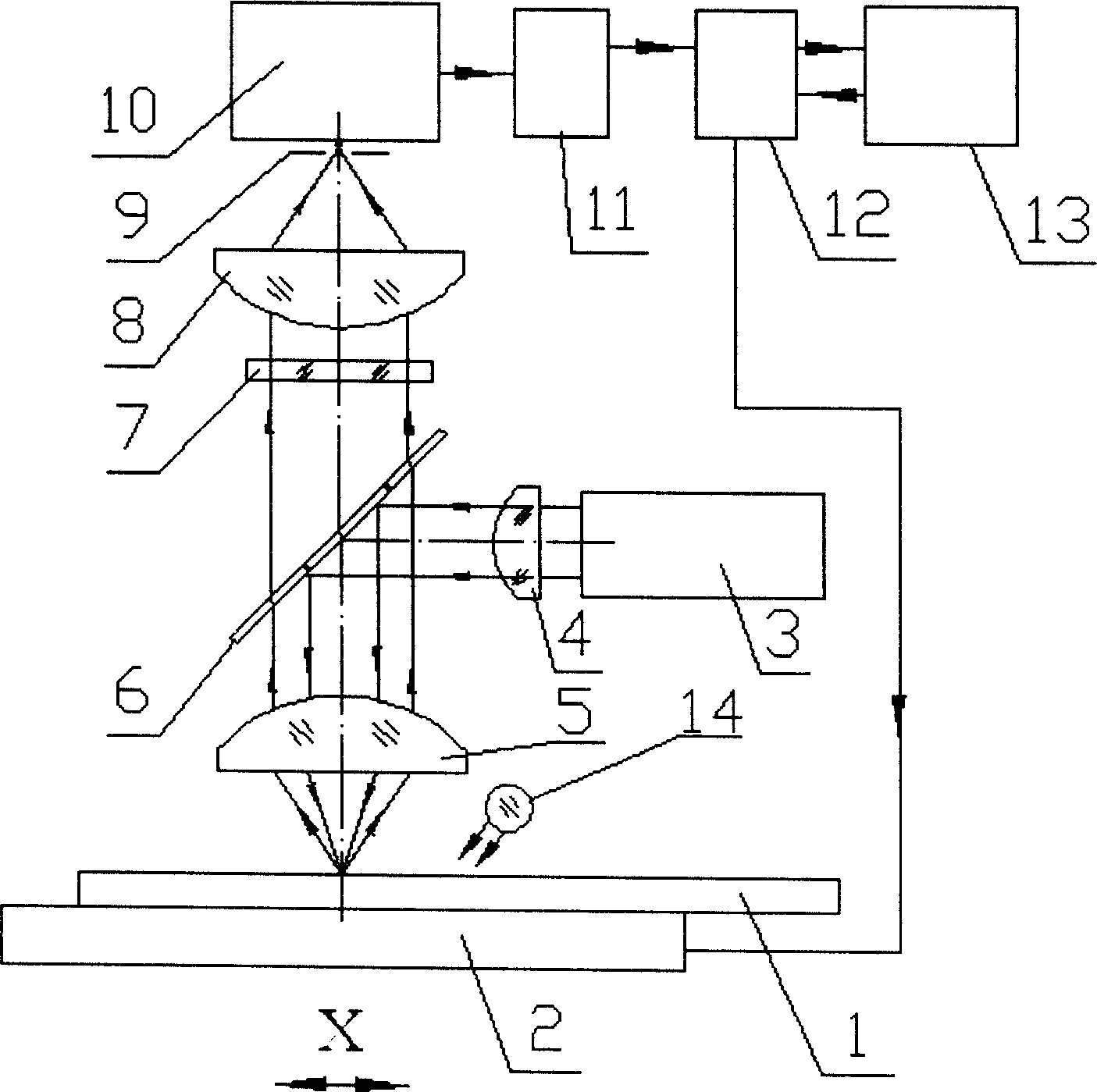
[0033] see figure 2 , figure 2 It is a schematic diagram of the structure and optical path of the best embodiment of the scanning type up-converting phosphorescent particle distribution state detector of the present invention. As can be seen from the figure, the scanning type up-transfer phosphorescent particle distribution state detector of the present invention is composed of an optical system, a scanning platform 2, a photoelectric conversion and signal processing system, and a data acquisition and control system; the photoelectric conversion and signal processing system It is composed of a photoelectric converter 10 and a preamplifier 11. The data acquisition and control system is composed of a multifunctional data acquisition card 12, an embedded computer 13 and processing software. It is characterized in that: the optical system is composed of a phosphorescence excitation optical path Composed of the phosphorescence receiving optical path, the phosphorescent excitatio...


PUM


Abstract

The invention relates to a scanning type upper rectification phosphorescence distributed tester, which comprises: a light-electricity changing and signal processing system, a data collecting and controlling system, a phosphorescence exciting light path and a phosphorescence receiving light path, wherein the phosphorescence exciting light path comprises an infrared semiconductor laser and a spherical adjusting mirror, a dichroic mirror and a focus / collimation lens and a scanning plane on the direction of the exciting light beam from the infrared semiconductor laser, wherein the scanning plane is used to lay the paper which is on the focus plane of the focus / collimation lens; the phosphorescence receiving light path is formed by the focus / collimation lens, the dichroic mirror, and a light filter, a rear focus mirror, an one-focus narrow slit baffle and the light-electricity changer; the one-focus narrow slit baffle is positioned on the rear focus plane of the rear focus mirror.

Description

technical field [0001] The invention relates to immunochromatography technology, in particular to a scanning type up-transfer phosphorescent particle distribution state detector. The detector can scan, detect and interpret the results of immunochromatographic test paper based on up-transfer phosphorescence technology, so as to realize the detection of pathogens, antigens, antibodies, illegal drugs, markers of major diseases (tumor, cancer and diabetes, etc.) Rapid, multiplexed, quantitative detection of substances. Background technique [0002] At present, in immunochromatography technology, enzymes, colloidal gold, and colored rubber beads are usually used as markers, and test strips are used as detection carriers. Visual methods, CCD and CMOS image sensors are usually used to detect the detection strips of test strips. The concentration of the target analyte in the sample can be determined by comparing the luminescence intensity of the marker on the quality control strip....

Claims


Application Information

Patent Timeline
Patent Type & Authority Applications(China)
IPC IPC(8): G01N21/64G01N15/00G01N33/558
Inventor 赵永凯周蕾王静黄立华闫中强胡孔新黄惠杰杨瑞馥李伟刘蕾王向朝王大宁王宝麟
Owner SHANGHAI INST OF OPTICS & FINE MECHANICS CHINESE ACAD OF SCI
Why Eureka
Try Eureka