This helps you quickly interpret patents by identifying the three key elements:
Problems solved by technology
Method used
Benefits of technology
Benefits of technology
[0015]A signal transmission device, which effectively reduces a influence of an external noise magnetic field, when the signal that is inputted into the pair of input terminals is transmitted to the pair of output terminals that are electrically insulated from the input terminals, is desired.
[0021]In the present invention, when the detection signals of the pair of magnetic sensors are added together, a signal in which the noise signal is canceled and the level of the essential signal is doubled can be obtained. By generating such signal, the signal that is outputted by the signal transmission device has an increased S / N ratio between the essential signal and the noise signal corresponding to the input signal. A signal transmission device which effectively reduces the influence of the noise magnetic field can be realized by using the principle of the present invention described above.
[0022]Depending on the arrangement or connection of the magnetic sensors, polarities of the essential signals, that are included in the detection signals outputted by the pair of magnetic sensors, are opposite to each other, and the noise signals having same polarity can be obtained. In this case, the same effect can be obtained by subtracting the detection signal of one of the magnetic sensor from the detection signal of the other magnetic sensor.
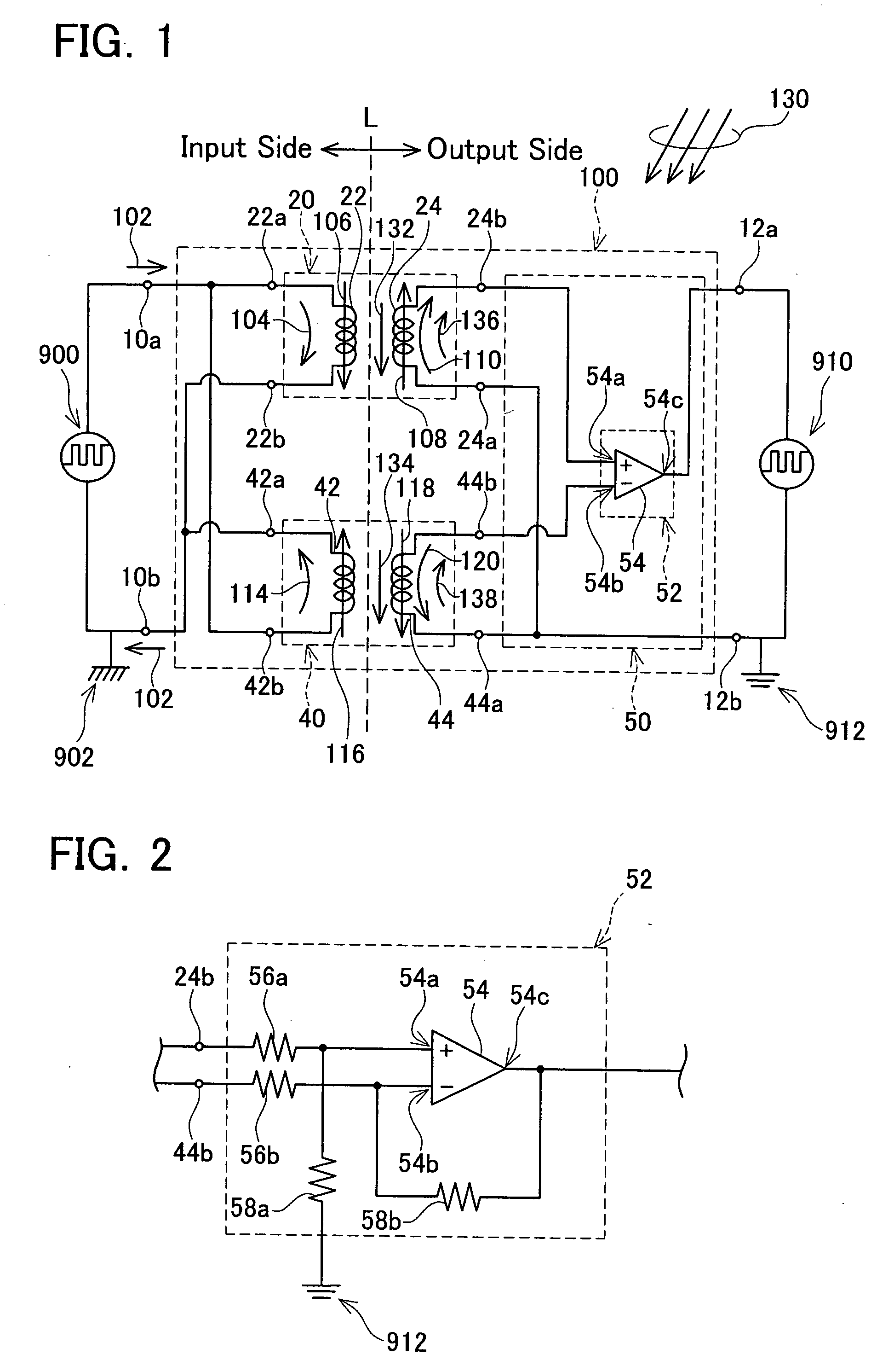
[0033]The signal output section determines the difference between the detection signals of the pair of the magnetic sensors. By determining the difference between the detection signals on the basis of the relationship between the abovementioned polarities, a signal in which the noise signal is canceled out and the level of the essential signal is doubled with respect to the level of the original essential signal, can be obtained. Therefore, the signal that is determined by signal output section is a signal which has a high S / N ratio. As a result, it is possible to realize a signal transmission device which reduces the influence of an external noise magnetic field and transmits a signal inputted to the pair of input terminals to the pair of output terminals without electrical connection between the pair of input terminals and the pair of output terminals.
[0035]It should be noted that it is preferred that the detection signals outputted by the pair of magnetic sensors be reduced by half and inputted to the signal output section. By reducing the detection signals outputted by the pair of magnetic sensors by half, it is possible to obtain a signal which has same amplitude as the input signal and in which the ratio of the noise signal to the essential signal is reduced (i.e., the signal has a high S / N ratio).
[0046]As described above, the present invention can realize a signal transmission device which effectively reduces the influence of an external noise magnetic field when transmitting a signal from the pair of input terminals to the pair of output terminals that are electrically insulated from the input terminals.
Problems solved by technology
When the S / N ratio decreases, a slight difference between the noise signal outputted by the dummy coil and the noise signal included in the detection signal outputted by the signal transmission section becomes significant.
Therefore, an input signal that is inputted into the pair of input terminals of the signal transmission device may not be transmitted accurately to the pair of output terminals.
Method used
Image
Click on the blue label to locate the original text in one second.
Reading with bidirectional positioning of images and text.
Examples
first embodiment
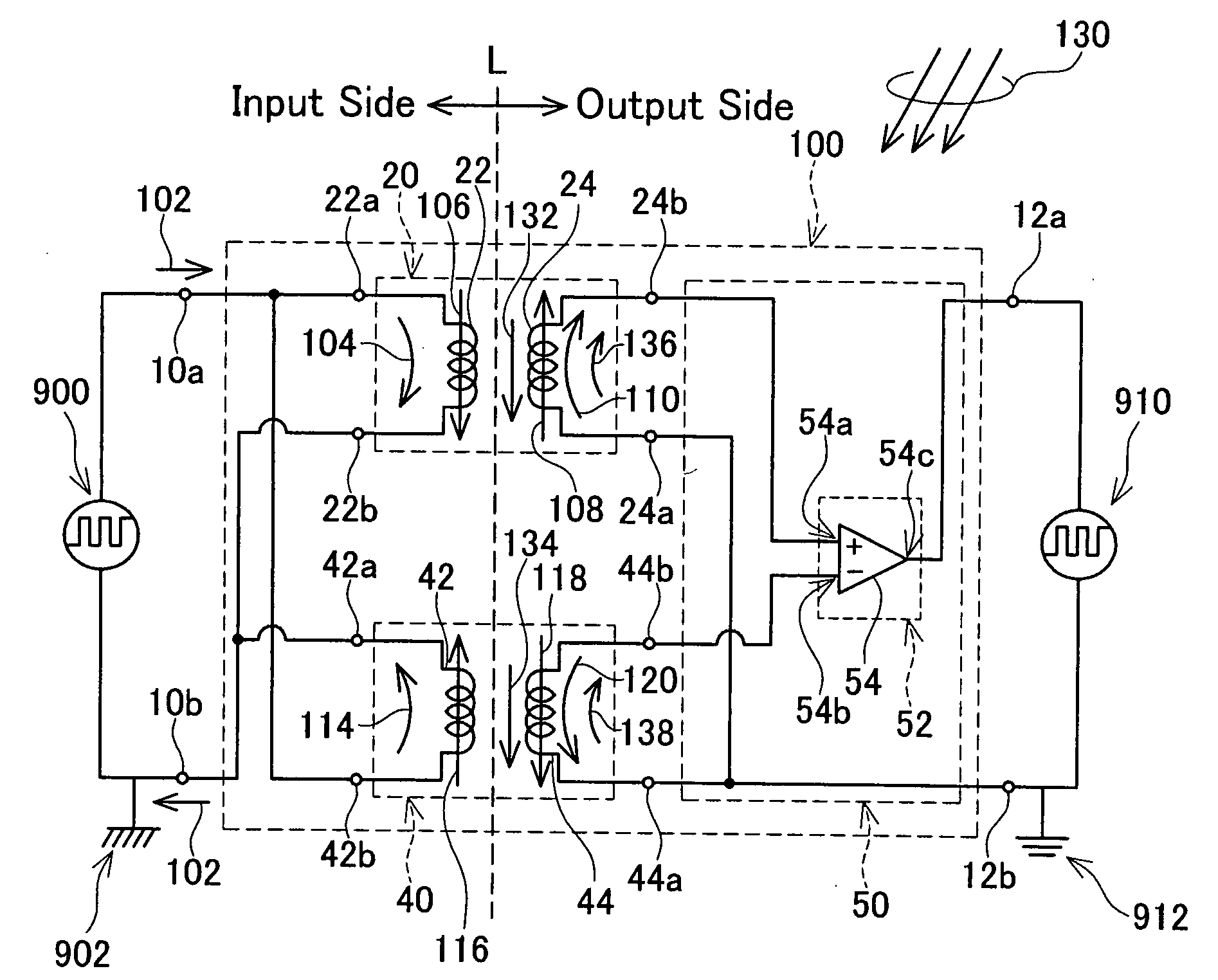
[0070]The signal transmission device of the first embodiment of the present invention is described with reference to the drawings. FIG. 1 is a circuit diagram of a signal transmission device 100 according to the first embodiment. The signal transmission device 100 has a pair of input terminals 10a, 10b, a pair of output terminals 12a, 12b, a pair of coils (a first input side coil 22, a second input side coil 42), a pair of detection coils (a first output side coil 24, a second output side coil 44), and a signal output section 50.
[0071]An external first circuit 900 can be connected between the pair of input terminals 10a, 10b. In the signal transmission device 100, the input side coils 22, 42 are connected between the pair of input terminals 10a, 10b.
[0072]An external second circuit 910 can be connected between the pair of output terminals 12a, 12b.
[0073]A first transformer 20 is formed by the first input side coil 22 and the first output side coil 24. Similarly, a second transform...
second embodiment
[0129]The second embodiment will be described. FIG. 4 shows a circuit diagram of a signal transmission device 100b according to the second embodiment. The signal transmission device 100b has the first transformer 20, second transformer 40 and signal output section 50. As with the signal transmission device 100 shown in FIG. 1, the first transformer 20 is formed by the first input side coil 22 and the first output side coil 24. The second transformer 40 is formed by the second input side coil 42 and the second output side coil 44.
[0130]The configuration on the right side of the broken line L in FIG. 4 (output side) is the same as the configuration on the output side of the signal transmission device 100 shown in FIG. 1. Therefore, in FIG. 4, the reference numerals for some components that are the same as those of the signal transmission device 100 of the first embodiment are omitted.
[0131]In the signal transmission device 100 shown in FIG. 1, the first input side coil 22 and the seco...
third embodiment
[0132]The third embodiment of the present invention will be described. FIG. 5 is a circuit diagram of a signal transmission device 100d according to the third embodiment. The signal transmission device 100d of the present embodiment has the pair of input terminals 10a, 10b, the pair of output terminals 12a, 12b, the pair of transformers (the first transformer 20, the second transformer 40), and a signal output section 50b. The first transformer 20 is formed by the first input side coil 22 and the first output side coil 24. The first output side coil 24 is electrically insulated from the input side coil 22 but joined therewith magnetically. The second transformer 40 is formed by the second input side coil 42 and the second output side coil 44. The second output side coil 44 is electrically insulated from the input side coil 42 but joined therewith magnetically.
[0133]In FIG. 5, the same components as those of the signal transmission device 100 shown in FIG. 1 are applied with the same...
PUM
Abstract
The invention provides a signal transmission device that transmits a signal applied to a pair of input terminals to a pair of output terminals insulated electrically from the pair of input terminals while reducing the influence of an external noisemagnetic field. The signal transmission device has a pair of coils, a pair of magnetic sensors and a signal output section. Each of the coils is connected between the pair of input terminals. Each of the coils generates a magnetic field respectively in response to the input signal applied between the pair of input terminals. A direction of the magnetic field generated by one of the coils is opposite to a direction of the magnetic field generated by the other of the coils. Each of the magnetic sensors corresponds to one of the coils exclusively. Each of the magnetic sensors detects the magnetic field generated by the corresponding coil, and outputs a detection signal in response to the detected magnetic field. The signal output section outputs an output signal to the pair of output terminals. The output signal corresponds to a difference between the pair of detection signals outputted by the pair of magnetic sensors. In the difference, the signal component caused by an external noise magnetic field is canceled. On the other hand, in the difference, the signal component caused by the input signal applied between the pair of input terminals are doubled with respect to the input signal. Thereby, the signal output section outputs the output signal with high S / N ratio.
Description
CROSS REFERENCE TO RELATED APPLICATION[0001]This application claims priority to Japanese Patent Application No. 2006-055318 filed on Mar. 1, 2006, the contents of which are hereby incorporated by reference into the present application.BACKGROUND OF THE INVENTION[0002]1. Field of the Invention[0003]The present invention relates to a signal transmission device that transmits an input signal from a pair of input terminals to a pair of output terminals that are electrically insulated from the pair of input terminals. Specifically, the present invention relates to a signal transmission device that can reduce the influence of an external noise magnetic field during signal transmission.[0004]2. Description of the Related Art[0005]Signal transmission devices for transmitting a signal from a pair of input terminals to a pair of output terminals that are electrically insulated from the input terminals are known. One of such signal transmission devices is a device for transmitting a signal usi...
Claims
Application Information
Patent Timeline
Application Date:The date an application was filed.
Publication Date:The date a patent or application was officially published.
First Publication Date:The earliest publication date of a patent with the same application number.
Issue Date:Publication date of the patent grant document.
PCT Entry Date:The Entry date of PCT National Phase.
Estimated Expiry Date:The statutory expiry date of a patent right according to the Patent Law, and it is the longest term of protection that the patent right can achieve without the termination of the patent right due to other reasons(Term extension factor has been taken into account ).
Invalid Date:Actual expiry date is based on effective date or publication date of legal transaction data of invalid patent.

