Fault diagnosis method and apparatus for rolling bearing

A technology for rolling bearings and faults, which is applied in the field of fault diagnosis of rolling bearings. It can solve the problems of not being able to get rid of hardware, extraction, and features that cannot be realized in early faults, so as to avoid the interference of human factors and improve the accuracy.

Active Publication Date: 2016-05-04
XINJIANG GOLDWIND SCI & TECH
View PDF7 Cites 39 Cited by
  • Summary
  • Abstract
  • Description
  • Claims
  • Application Information

AI Technical Summary

Problems solved by technology

[0004] However, the above method has the following disadvantages: firstly, the hardware order and calculation order cannot get rid of the hardware dependence; secondly, the common instantaneous frequency estimation method needs to a

Method used


Image

  • Fault diagnosis method and apparatus for rolling bearing
  • Fault diagnosis method and apparatus for rolling bearing
  • Fault diagnosis method and apparatus for rolling bearing

Examples


Embodiment 1

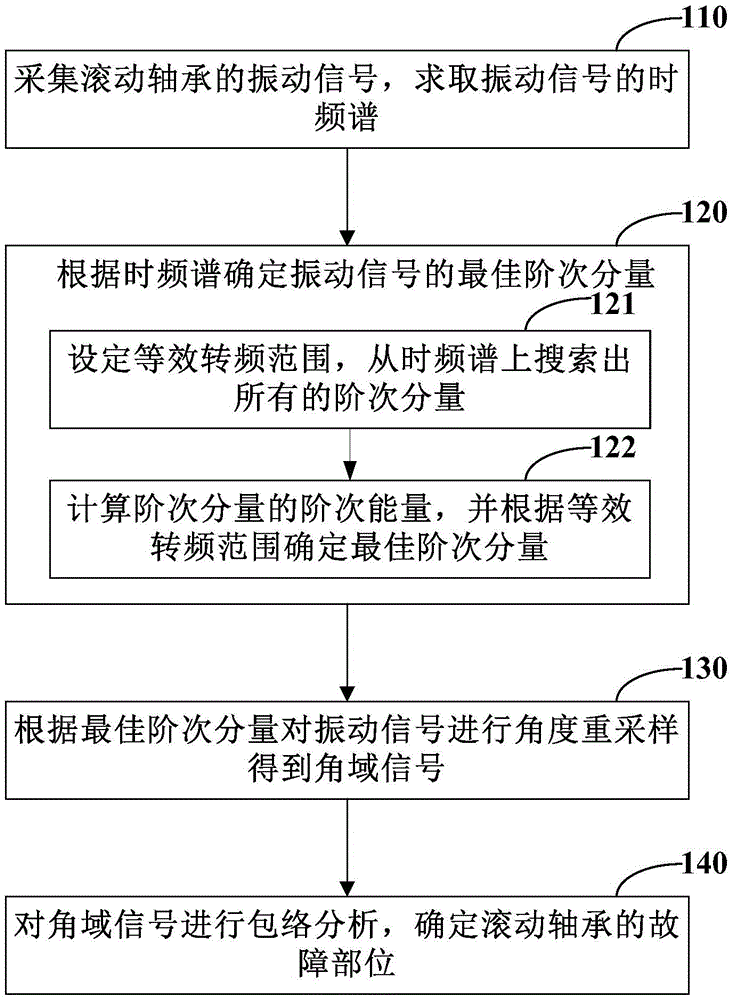
[0023] figure 1 It is a schematic flow chart of the rolling bearing fault diagnosis method in Embodiment 1 of the present invention, such as figure 1 As shown, the fault diagnosis methods of rolling bearings include:

[0024] Step 110: Collect the vibration signal of the rolling bearing, and obtain the time-frequency spectrum of the vibration signal.

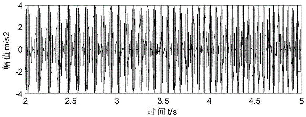
[0025] In a specific implementation manner, an acceleration sensor may be installed at the measuring position on the rolling bearing seat, and the vibration signal of the rolling bearing may be collected through the provided acceleration sensor. figure 2 is the waveform diagram of the simulated vibration signal of the rolling bearing, the simulated vibration signal is expressed by the following formula (1), where t is the time and X(t) is the amplitude:

[0026] X(t)=(1+sin(4πt 2 ))×sin(332πt 2 )………………………………………Formula 1)

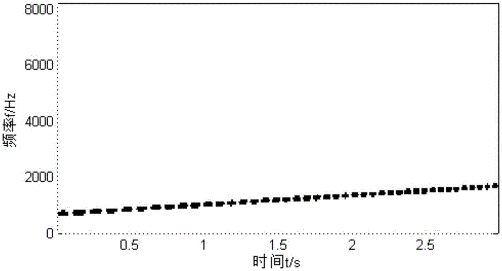
[0027] One of the following methods can be used to obtain the time-frequency spectrum of the vibratio...

Embodiment 2

[0072] Figure 12 It is a schematic structural diagram of a rolling bearing fault diagnosis device according to Embodiment 2 of the present invention. It can be used to execute the steps of the method for diagnosing the rolling bearing in Embodiment 1 of the present invention.

[0073] refer to Figure 12 , the rolling bearing fault diagnosis device includes a signal acquisition and spectrum acquisition module 1210 , an order component determination module 1220 , an angle resampling module 1230 and a fault diagnosis module 1240 .

[0074] The signal collection module 1210 is used to collect the vibration signal of the rolling bearing, and obtain the time-frequency spectrum of the vibration signal.

[0075] The order component determination module 1220 is used to determine the optimal order component of the vibration signal according to the time-frequency spectrum.

[0076] Specifically, the order component determination module 1220 includes:

[0077] The conversion frequen...


PUM


Abstract

The embodiments of the invention provide a fault diagnosis method and apparatus for a rolling bearing. The fault diagnosis method for the rolling bearing comprises the following steps: acquiring vibration signals of the rolling bearing, and solving a time-frequency spectrum of the vibration signals; according to the time-frequency spectrum, determining an optimal order component of the vibration signals; according to the optimal order component, performing angle re-sampling on the vibration signals to obtain angle domain signals; and performing envelope analyzing on the angle domain signals, and determining fault positions of the rolling bearing, wherein determination of the optimal order component comprises: setting an equivalent frequency conversion scope and searching for all order components from the time-frequency spectrum; and calculating order energy of the order components and determining the optimal order component from the equivalent frequency conversion scope. The fault diagnosis method and apparatus for the rolling bearing realize automatic and rapid determination of the optimal order component so as to provide a basis for fault diagnosis of the rolling bearing, improve the fault diagnosis accuracy and avoid interference of manual factors.

Description

technical field [0001] The invention relates to the technical field of mechanical fault monitoring, in particular to a fault diagnosis method and device for rolling bearings. Background technique [0002] In industrial applications, rolling bearings are vulnerable parts as well as critical monitoring components, and thus require fault diagnosis. Taking the rolling bearing of a wind turbine as an example, due to the low speed of the main shaft of the direct drive wind turbine, the fault characteristic frequency of the rolling bearing is in a low frequency band, and the early fault characteristics are relatively weak. In addition, due to large changes in wind speed, wind turbines generally work under variable speed conditions, which increases the difficulty of rolling bearing fault diagnosis. [0003] The order analysis technique is a common method to solve the fault diagnosis of rolling bearings under the condition of variable speed. Specifically, the rotational speed signa...

Claims


Application Information

Patent Timeline
IPC IPC(8): G01M13/04
CPCG01M13/045
Inventor 丁雪娟曹博李玉奎
Owner XINJIANG GOLDWIND SCI & TECH
Why Eureka
Try Eureka