
Indoor heat environment comfort evaluation thermal manikin system and indoor heat environment comfort evaluation method

A heating dummy and thermal environment technology, applied in material thermal analysis, measuring devices, instruments, etc., can solve the problems of low sensor accuracy, ill-considered environmental parameters, and actual feeling errors.

Pending Publication Date: 2017-08-08
CHINA NAT INST OF STANDARDIZATION +2
View PDF7 Cites 13 Cited by
  • Summary
  • Abstract
  • Description
  • Claims
  • Application Information

AI Technical Summary

Problems solved by technology

However, the existing thermal comfort detection and evaluation technology has problems such as poor mobility, low sensor accuracy, and poor consideration of environmental parameters; especially the PMV evaluation index used in the existing thermal comfort evaluation is based on The calculation of the temperature at a certain point or the average temperature of several points cannot truly reflect the surrounding environment of the human body. There is still a large error between the obtained evaluation result and the actual feeling of the real environment where the human body is actually located, so that the evaluation result The accuracy is not high; when using PMV evaluation at the same time, it is necessary to test multiple parameters, such as the heat consumed by external work, the average radiation temperature, the indoor air flow rate and the partial pressure of water vapor, etc. The workload is large and the cost is high

Method used


Image

  • Indoor heat environment comfort evaluation thermal manikin system and indoor heat environment comfort evaluation method
  • Indoor heat environment comfort evaluation thermal manikin system and indoor heat environment comfort evaluation method
  • Indoor heat environment comfort evaluation thermal manikin system and indoor heat environment comfort evaluation method

Examples


Embodiment Construction

[0083] The technical solutions in the embodiments of the present invention will be clearly and completely described below, obviously, the described embodiments are only some of the embodiments of the present invention, not all of the embodiments. All other embodiments obtained by persons of ordinary skill in the art based on the embodiments of the present invention belong to the protection scope of the present invention.

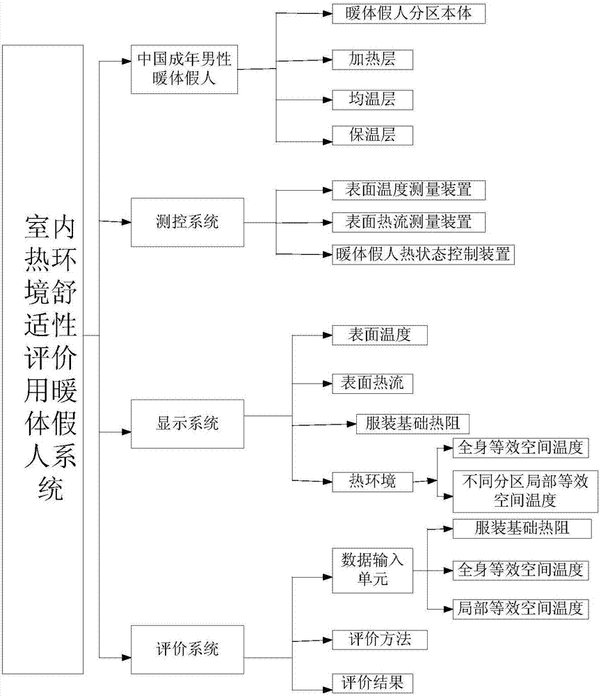
[0084] Such as figure 1As shown, the present invention provides a thermal manikin system for indoor thermal environment comfort evaluation, including a thermal manikin, a measurement and control system, and an evaluation system. The thermal manikin includes a thermal manikin body, and the thermal manikin According to the heat transfer characteristics of the actual human body, the body is divided into multi-section partition bodies, and the heating layer, temperature uniform layer and insulation layer are arranged in sequence on the inside of each partition b...


PUM


Abstract

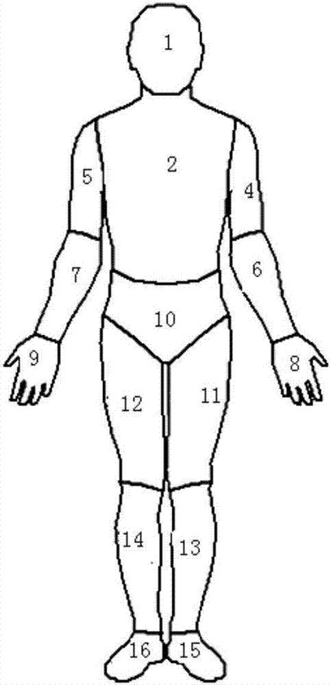
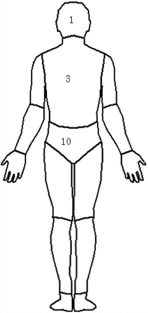
The invention provides an indoor heat environment comfort evaluation thermal manikin system and an indoor heat environment comfort evaluation method. The indoor heat environment comfort evaluation thermal manikin system comprises a thermal manikin, a measuring and control system and an evaluation system. The thermal manikin has good joint motion capability, and has 16 independent measuring and heating control split regions; the split regions sufficiently consider the physiological structure characteristics of a human body and the heat exchange characteristics of the human body in the heat environment with the environment. The indoor heat environment comfort evaluation thermal manikin system has the advantages that the application range is wide; the system can be applied to heat environment in various fields such as civil use, military use, aero-space and navigation; the heat environment parameters can be directly and accurately measured; the heat environment comfort can be objectively evaluated; the test and the evaluation result is stable and accurate; the repeatability is high; the indoor heat environment comfort evaluation thermal manikin system conforms to the real human body heat state; the reasonableness and the reliability are realized.

Description

technical field [0001] The invention relates to an indoor thermal environment evaluation system, in particular to a thermal manikin system and an evaluation method for indoor thermal environment comfort evaluation. Background technique [0002] With the development of economy and technology and the continuous improvement of living standards, people have higher and higher requirements for thermal comfort of indoor environment. Therefore, various environmental control systems have been developed and applied, and the evaluation methods and technical capabilities of thermal environment comfort are becoming more and more important. more attention. [0003] Thermal comfort refers to people's subjective satisfaction with a hot and humid environment. It is usually evaluated by Predicted Mean Vote PMV and Predicted Percentage of Dissatisfied PPD. The main factors affecting thermal comfort are air temperature, air relative humidity, average radiant temperature, relative air velocity...

Claims


Application Information

Patent Timeline
IPC IPC(8): G01N25/00
CPCG01N25/00
Inventor 赵朝义呼慧敏邱义芬罗虹王瑞张佳峥葛猛
Owner CHINA NAT INST OF STANDARDIZATION
Learn More