Conveyor belt management system

a conveyor belt and management system technology, applied in the field of conveyor belt management system, can solve the problems of cutting the core of the conveyor belt, damage to the conveyor belt, and the surface of the upper cover rubber being cut, so as to prevent the unusability of the conveyor belt. the effect of reducing the number of cuts

Active Publication Date: 2020-05-21
YOKOHAMA RUBBER CO LTD
View PDF0 Cites 0 Cited by
  • Summary
  • Abstract
  • Description
  • Claims
  • Application Information

AI Technical Summary

Benefits of technology

[0014]According to an embodiment of the present invention, to monitor the state of the conveyor belt, in addition to the indicator indicating the state of the belt conveyor device and the indicator indicating the use environment of the conveyor belt at the use site, at least one input item from five input items consisting of an amount of wear of an upper cover rubber of the conveyor belt, an impact force acting on the conveyor belt, a tensile force, an indicator indicating a state of a core, and an indicator indicating a state of an endless portion is used. Accordingly, the state of the conveyor belt can be determined in more detail than in the related art. This is advantageous in that the conveyor belt becoming unusable is more reliably prevented.

Problems solved by technology

The conveyed objects fed onto the upper cover rubber impact against the upper cover rubber, and conveyed objects that are sharp can cause cuts in the surface of the upper cover rubber.
The core of the conveyor belt may be cut due to flexural fatigue or abnormal tensile forces.
In addition to the above, damage to the conveyor belt may be caused by many factors, and if the damage is great, the conveyor belt becomes unusable.
If a conveyor belt becomes unusable, the belt line is stopped, and the conveying of the conveyed objects is significantly affected.
However, there are various other factors such as those described above, not only wear, that actually render the conveyor belt unusable.

Method used


Image

  • Conveyor belt management system
  • Conveyor belt management system
  • Conveyor belt management system

Examples


Embodiment Construction

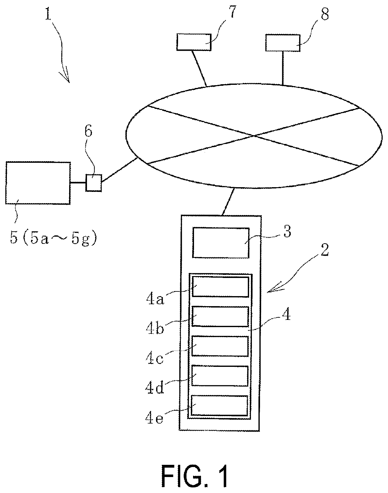
[0023]A conveyor belt management system according to embodiments of the present invention will be described below with reference to the drawings.

[0024]A conveyor belt management system 1 (hereinafter referred to as management system 1) according to an embodiment of the present invention illustrated in FIG. 1 monitors the use state of a conveyor belt 12 installed on a belt conveyor device 9 at a use site illustrated in FIGS. 6 and 7.

[0025]In the belt conveyor device 9, the conveyor belt 12 is mounted around a drive pulley 10a and a driven pulley 10b at a predetermined tension. Between the drive pulley 10a and the driven pulley 10b, the conveyor belt 12 is supported by support rollers 10c disposed at appropriate intervals in the belt longitudinal direction.

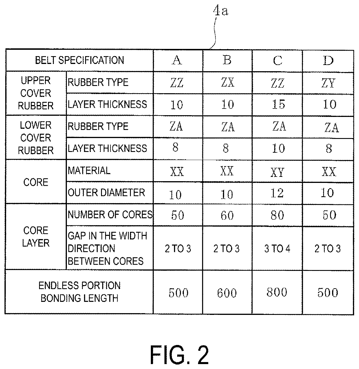
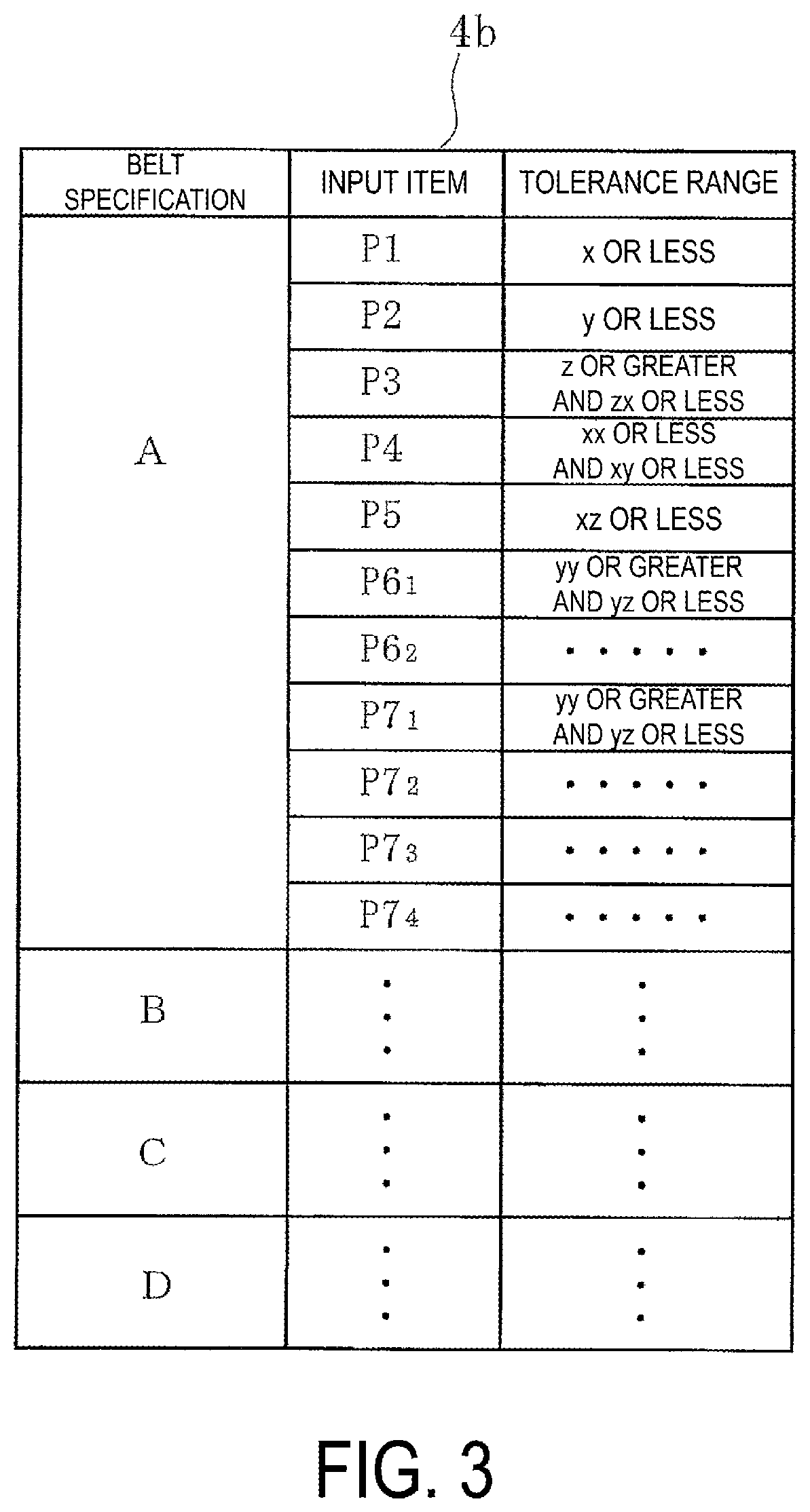
[0026]The conveyor belt 12 is constituted by a core layer 14 including a core 15 made of a steel cord or canvas, and an upper cover rubber 13a and a lower cover rubber 13b that sandwich the core layer 14 therebetween. The core layer...


PUM


Abstract

A conveyor belt management system is capable of determining in detail the state of a conveyor belt. A state of the conveyor belt is monitored by a calculation unit based on data of an indicator indicating a status of a belt conveyor device and data of an indicator indicating a use environment of the conveyor belt installed on a belt conveyor device; at least one data from an amount of wear of an upper cover rubber, an impact force acting on the conveyor belt, a tensile force, an indicator indicating a state of a core, and an indicator indicating a state of an endless portion input to the server by the input unit; and a belt specification database and a tolerance range database in which a tolerance range for each of the input items is input in advance per belt specification stored in a storage unit.

Description

TECHNICAL FIELD[0001]The present invention relates to a conveyor belt management system and particularly relates to a conveyor belt management system capable of determining in detail the state of a conveyor belt and reliably preventing the conveyor belt becoming unusable.BACKGROUND ART[0002]Various conveyed objects, including mineral resources such as iron ore and limestone, are conveyed by a conveyor belt. An upper cover rubber of a conveyor belt is worn over time by conveyed objects being fed onto the upper cover rubber. The conveyed objects fed onto the upper cover rubber impact against the upper cover rubber, and conveyed objects that are sharp can cause cuts in the surface of the upper cover rubber. The core of the conveyor belt may be cut due to flexural fatigue or abnormal tensile forces. In addition to the above, damage to the conveyor belt may be caused by many factors, and if the damage is great, the conveyor belt becomes unusable.[0003]If a conveyor belt becomes unusable,...

Claims


Application Information

Patent Timeline
Patent Type & Authority Applications(United States)
IPC IPC(8): G06Q10/00G06Q10/08B65G43/02
CPCB65G43/02G06Q10/20G06Q10/087G06Q10/00
Inventor HOU, GANG
Owner YOKOHAMA RUBBER CO LTD
Why Eureka
Try Eureka