Conveyor belt management system

Active Publication Date: 2020-05-21
YOKOHAMA RUBBER CO LTD
View PDF4 Cites 2 Cited by
  • Summary
  • Abstract
  • Description
  • Claims
  • Application Information

AI Technical Summary

Benefits of technology

The present invention provides a method for monitoring the state of a conveyor belt by using various indicators such as wear of the rubber cover, impact force, tensile force, and indicators for the core and endless portion of the belt. This allows the conveyor belt to be monitored in more detail and prevents it from becoming unusable. Additionally, the expected service life of the conveyor belt can be calculated based on various factors, which helps in determining the replacement period and reducing excess inventory and running costs.

Problems solved by technology

The conveyed objects fed onto the upper cover rubber impact against the upper cover rubber, and conveyed objects that are sharp can cause cuts in the surface of the upper cover rubber.
The core of the conveyor belt may be cut due to flexural fatigue or abnormal tensile forces.
In addition to the above, damage to the conveyor belt may be caused by many factors, and if the damage is excessive, the conveyor belt becomes unusable.
If a conveyor belt becomes unusable, the belt line is stopped, and the conveying of the conveyed objects is significantly affected.
However, there are various other factors such as those described above, not only wear, that actually render the conveyor belt unusable.
As a result, running costs are greatly increased.
Furthermore, if the type of conveyed objects conveyed by the conveyor belt changes, the replacement conveyor belts in inventory may not be used.
However, the management system proposed in Patent Document 1 is not capable of determining the remaining service life unless the conveyor belt has been used and the rubber worn a certain amount.
Additionally, when the amount of wear of the rubber is low, the prediction accuracy of the remaining service life is low.

Method used


Image

  • Conveyor belt management system
  • Conveyor belt management system
  • Conveyor belt management system

Examples


Embodiment Construction

[0027]A conveyor belt management system according to embodiments of the present invention will be described below with reference to the drawings.

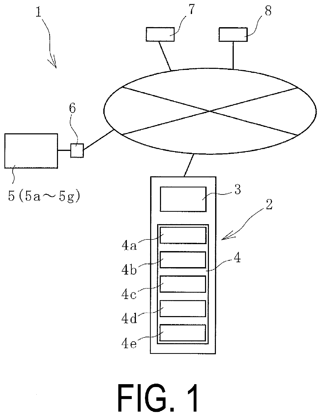
[0028]A conveyor belt management system 1 (hereinafter referred to as management system 1) according to an embodiment of the present invention illustrated in FIG. 1 monitors the use state of a conveyor belt 12 installed on a belt conveyor device 9 at a use site illustrated in FIGS. 6 and 7. The management system 1 calculates an expected service life Jf before the conveyor belt 12 is used. In this embodiment, a remaining service life Ja is calculated during the use period of the conveyor belt 12.

[0029]In the belt conveyor device 9, the conveyor belt 12 is mounted around a drive pulley 10a and a driven pulley 10b at a predetermined tension. Between the drive pulley 10a and the driven pulley 10b, the conveyor belt 12 is supported by support rollers 10c disposed at appropriate intervals in the belt longitudinal direction.

[0030]The conveyor belt...


PUM


Abstract

A conveyor belt management system is capable of determining in detail the state of a conveyor belt, more reliably preventing the conveyor belt becoming unusable, determining a suitable replacement period, and lowing the running costs of the conveyor belt. A state of the conveyor belt is monitored by a calculation unit and an expected service life before use is calculated based on data of an indicator indicating a status of a belt conveyor device and an indicator indicating a use environment of the conveyor belt; at least one data from an amount of wear, an impact force, a tensile force, a state of a core, and an indicator indicating a state of an endless portion; and a belt specification database and a tolerance range database in which a tolerance range for each of the input items in input in advance per belt specification stored in a storage unit.

Description

TECHNICAL FIELD[0001]The present invention relates to a conveyor belt management system and particularly relates to a conveyor belt management system capable of determining in detail the state of a conveyor belt, reliably preventing the conveyor belt becoming unusable, determining a suitable replacement period of the conveyor belt as early as possible, and lowering the running costs of the conveyor belt.BACKGROUND ART[0002]Various conveyed objects, including mineral resources such as iron ore and limestone, are conveyed by a conveyor belt. An upper cover rubber of a conveyor belt is worn over time by conveyed objects being fed onto the upper cover rubber. The conveyed objects fed onto the upper cover rubber impact against the upper cover rubber, and conveyed objects that are sharp can cause cuts in the surface of the upper cover rubber. The core of the conveyor belt may be cut due to flexural fatigue or abnormal tensile forces. In addition to the above, damage to the conveyor belt m...

Claims


Application Information

Patent Timeline
IPC IPC(8): B65G43/02G05B23/02G06Q10/00G06Q10/08
CPCB65G2203/042B65G43/02G06Q10/20G06Q10/087G05B23/0283B65G2203/0275G06Q10/00
Inventor HOU, GANG
Owner YOKOHAMA RUBBER CO LTD
Why Eureka
Try Eureka