
Beer bubbling device

a technology of bubbling device and beer, which is applied in the direction of liquid transfer device, volume metering, instruments, etc., can solve the problem of not being able to obtain the proper amount of froth, and achieve the effect of simple structure, no time-consuming, and easy switching

Inactive Publication Date: 2011-05-19
LEAD
View PDF37 Cites 7 Cited by
  • Summary
  • Abstract
  • Description
  • Claims
  • Application Information

AI Technical Summary

Benefits of technology

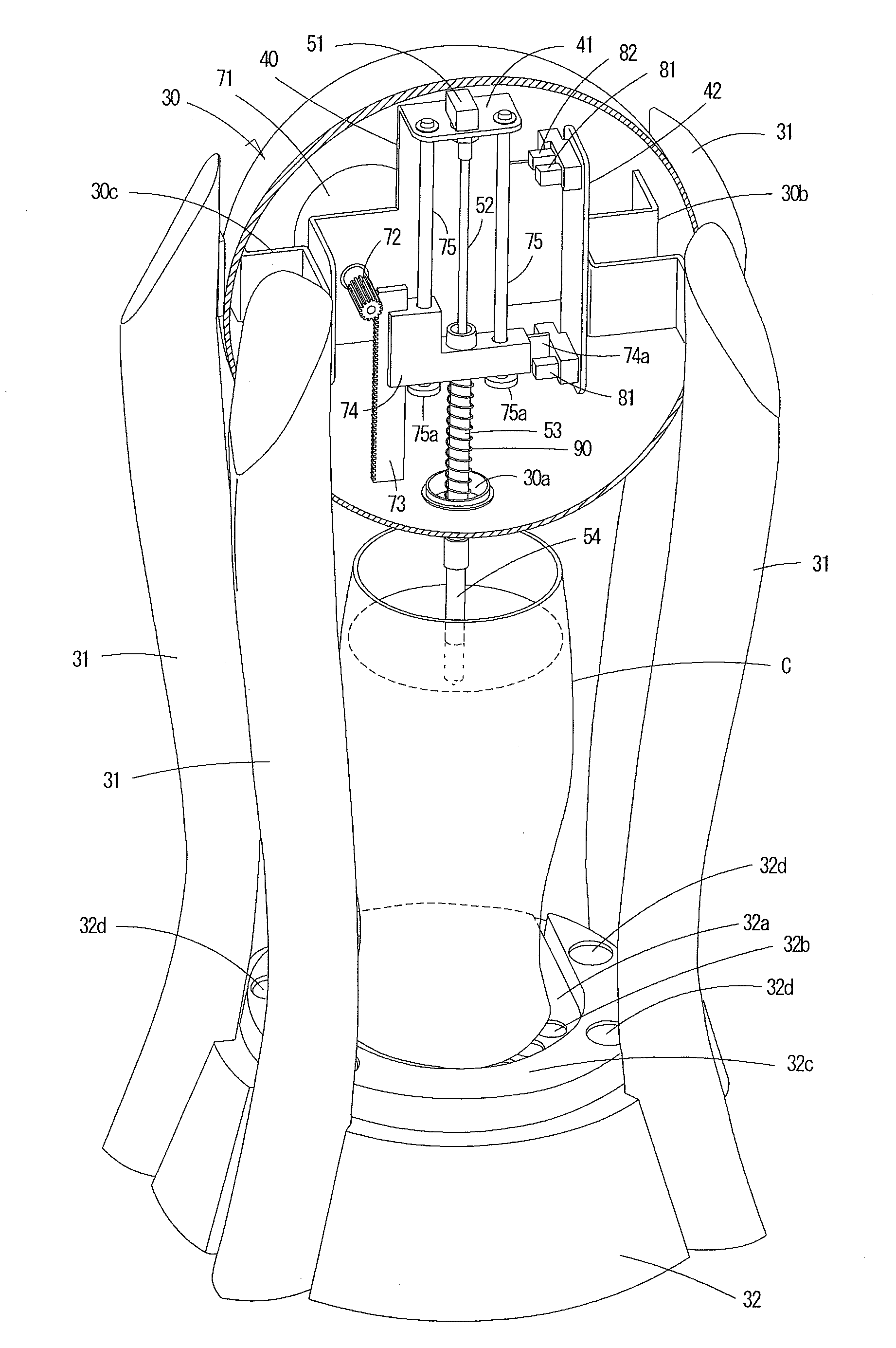
The present invention relates to a beer frothing device that automatically generates froth by squirting a pressurized gas into beer. The device includes a pressurized gas supply, a squirting mechanism, a lifting mechanism, and a cutoff valve. The device is designed to stably generate froth without degrading the quality of the beer. The device can be used in businesses to enhance the value of beer sales. The technical effect of the invention is to provide a simple and efficient way to generate froth in beer without adding extra costs or requiring additional skills.

Problems solved by technology

A proper amount of froth cannot be obtained if the temperature of beer is very low, or depending on the frequency of beer servings.

Method used


Image

  • Beer bubbling device
  • Beer bubbling device
  • Beer bubbling device

Examples


Embodiment Construction

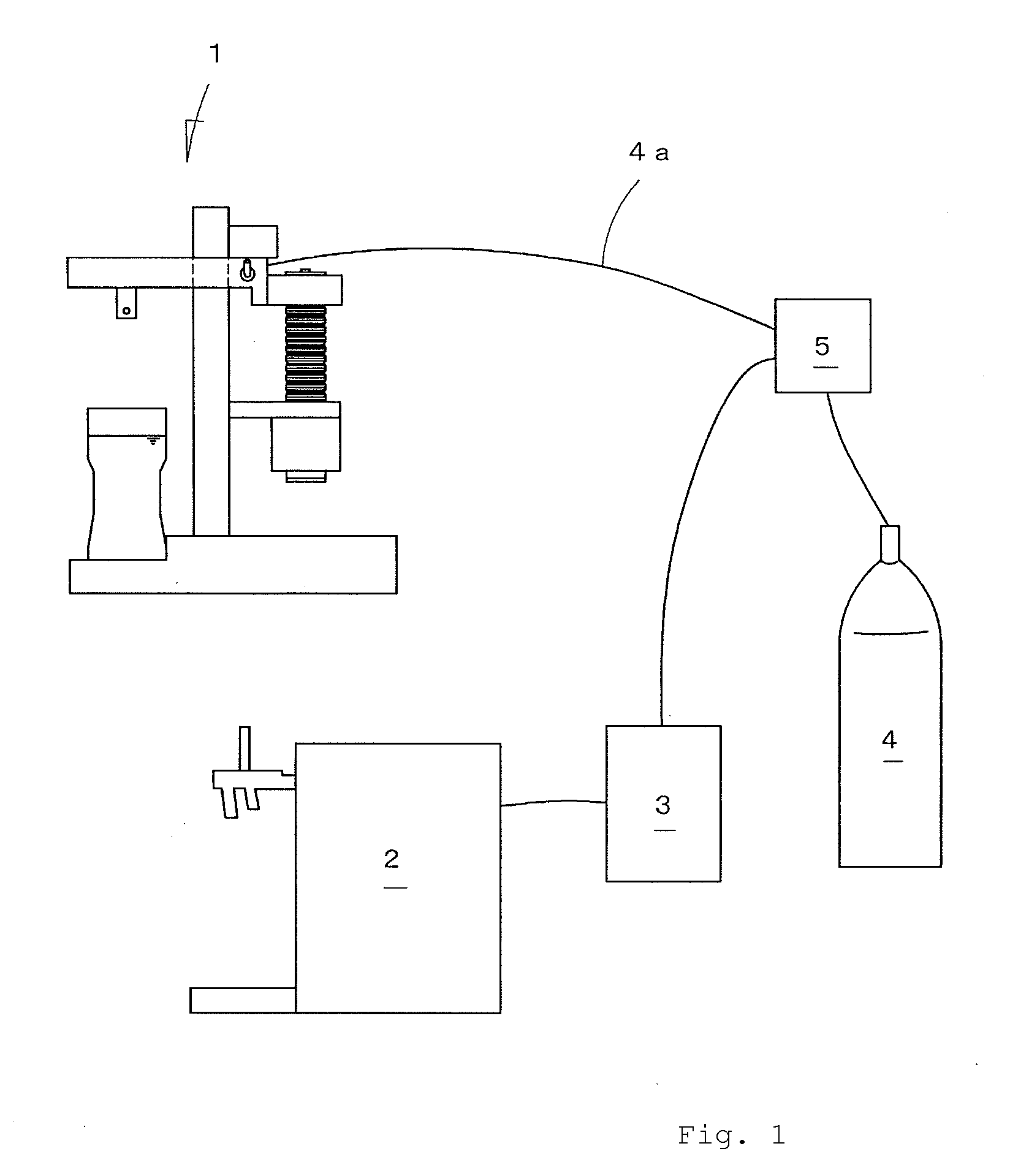
[0055]The preferred embodiments of the present invention are described below with reference to the drawings. First, FIG. 1 illustrates an installation example of the present invention. Referring to FIG. 1, there are shown a frothing device 1, an existing beer server machine 2, a beer keg 3 connected to the beer server machine 2, and a carbon dioxide cylinder 4. The carbon dioxide cylinder 4 is connected to the beer keg 3 and the connection of the carbon dioxide cylinder 4 is branched with a branch line 4a thereof connected the frothing device 1. A pressure reducing valve reduces the supply gas pressure of the carbon dioxide cylinder 4 to a set pressure. In this embodiment, the pressure reducing valve 5 of one-input and two-output type is arranged at a branch point, and reduces the supply gas pressure to different pressures for the beer keg 3 and the frothing device 1. More specifically, the pressure reducing valve 5 sets the pressure to the beer keg 3 so that beer is supplied to the...


PUM

PropertyMeasurementUnit
depthaaaaaaaaaa
heightaaaaaaaaaa
forceaaaaaaaaaa

Abstract

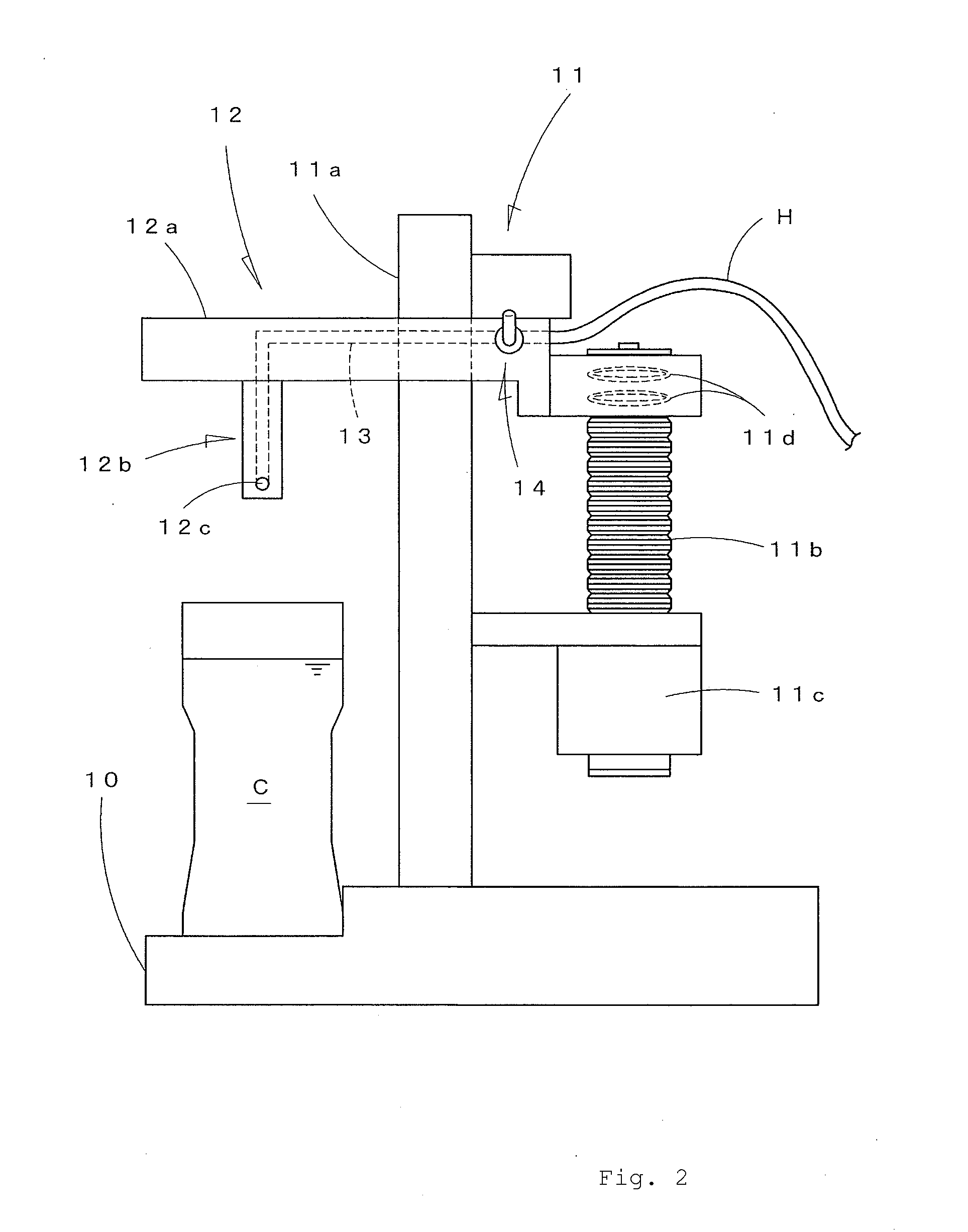
A beer frothing device for stably generating froth without degrading beer quality is provided. The device frothing beer in a vessel by squirting a pressurized gas through a nozzle submerged in the beer, includes a pressurized gas supply, a squirting mechanism, connected to the gas supply and having a cutoff valve to obstruct the gas squirting through the nozzle, a lifting mechanism for supporting the squirting mechanism during its vertically reciprocating up-and-down movement with a half track between a start point where the nozzle is positioned right above the vessel and a lower point where the nozzle is submerged at a predetermined depth in the beer, a start switch for lowering the lifting mechanism, a direction change switch for raising the lifting mechanism when the lower point is detected during lowering operation, a stop switch for stopping the lifting mechanism when the start point is detected during rising operation, and an open-valve switch, arranged between the direction change switch and the stop switch, for opening the cutoff valve to detect an appropriate position where the nozzle is submerged in the beer. The direction change switch and the stop switch make a limit switch.

Description

TECHNICAL FIELD[0001]The present invention relates to a technique for generating froth by blowing carbon dioxide gas into beer and, more in detail, to a beer frothing device for automatically generating froth by simply setting a glass of beer or the like.BACKGROUND ART[0002]When people drink a glass or mug of beer, frothing beer is believed to be preferable in terms of taste and eye-pleasing point of view. An amount of froth should not be so large but not so small, and a ratio of froth of 7:3 is said to be ideal. At any rate, when beer is provided in business such as in restaurants, applying an appropriate amount of froth is essential to heighten commercial value of beer.[0003]A large number of inventions have been developed to generate froth in beer. One of the currently available and typical techniques is a beer server machine which has a nozzle with two output openings, one for beer and the other for froth. A stopcock is opened to one side to allow beer to be fed to a glass or th...

Claims


Application Information

Patent Timeline
Patent Type & Authority Applications(United States)
IPC IPC(8): C12G3/04
CPCB67D1/0071B67D1/025B67D1/0406C12G3/04B67D1/1275A47J31/4496B67D1/0894B67D1/07B67D1/08B67D1/12
Inventor ISHIDA, HIROSHIUCHIDA, AKIHIKOINOUE, TOMOHIRO
Owner LEAD
Learn More