Audio encoder and decoder using a frequency domain processor , a time domain processor, and a cross processing for continuous initialization

a frequency domain and encoder technology, applied in the field of audio signal encoding and decoding, can solve the problems of reducing audio quality, reducing the accuracy of known frequency domain encoders, and reducing audio quality

Active Publication Date: 2019-03-19
FRAUNHOFER GESELLSCHAFT ZUR FOERDERUNG DER ANGEWANDTEN FORSCHUNG EV
View PDF47 Cites 5 Cited by
  • Summary
  • Abstract
  • Description
  • Claims
  • Application Information

AI Technical Summary

Benefits of technology

[0040]Furthermore, it is advantageous to use tile pruning and stabilization in order to make sure that artifacts created by fast changing source regions for the same reconstruction region or target region are avoided. To this end, a similarity analysis among the different identified source regions is performed and when a source tile is similar to other source tiles with a similarity above a threshold, then this source tile can be dropped from the set of potential source tiles since it is highly correlated with other source tiles. Furthermore, as a kind of tile selection stabilization, it is advantageous to keep the tile order from the previous frame if none of the source tiles in the current frame correlate (better than a given threshold) with the target tiles in the current frame.
[0043]In an implementation, it is advantageous to use complex TNS / TTS filtering. Thereby, the (temporal) aliasing artifacts of a critically sampled real representation, like MDCT, are avoided. A complex TNS filter can be calculated on the encoder-side by applying not only a modified discrete cosine transform but also a modified discrete sine transform in addition to obtain a complex modified transform. Nevertheless, only the modified discrete cosine transform values, i.e., the real part of the complex transform is transmitted. On the decoder-side, however, it is possible to estimate the imaginary part of the transform using MDCT spectra of preceding or subsequent frames so that, on the decoder-side, the complex filter can be again applied in the inverse prediction over frequency and, specifically, the prediction over the border between the source range and the reconstruction range and also over the border between frequency-adjacent frequency tiles within the reconstruction range.
[0045]In further embodiments, the time domain encoding / decoding processor relies on a lower sampling rate and the corresponding bandwidth extension functionality.
[0046]In further embodiments, a cross-processor is provided in order to initialize the time domain encoder / decoder with initialization data derived from the currently processed frequency domain encoder / decoder signal This allows that when the currently processed audio signal portion is processed by the frequency domain encoder, the parallel time domain encoder is initialized so that when a switch from the frequency domain encoder to a time domain encoder takes place, this time domain encoder can immediately start processing since all the initialization data relating to earlier signals are already there due to the cross-processor. This cross-processor is advantageously applied on the encoder-side and, additionally, on the decoder-side and advantageously uses a frequency-time transform which additionally performs a very efficient downsampling from the higher output or input sampling rate into the lower time domain core coder sampling rate by only selecting a certain low band portion of the domain signal together with a certain reduced transform size. Thus, a sample rate conversion from the high sampling rate to the low sampling rate is very efficiently performed and this signal obtained by the transform with the reduced transform size can then be used for initializing the time domain encoder / decoder so that the time domain encoder / decoder is ready to immediately perform time domain encoding when this situation is signaled by a controller and the immediately preceding audio signal portion was encoded in the frequency domain.

Problems solved by technology

In particular when lowest bit rates are to be achieved, the employed coding leads to a reduction of audio quality that often is primarily caused by a limitation at the encoder side of the audio signal bandwidth to be transmitted.
However, specifically for non-speech signals having prominent harmonics in the high frequency band, the known frequency domain encoders have a reduced accuracy and, therefore, a reduced audio quality due to the fact that such prominent harmonics can only be separately parametrically encoded or are eliminated at all in the encoding / decoding process.
This bandwidth extension functionality increases the bitrate efficiency but, on the other hand, introduces further inflexibility due to the fact that both encoding branches, i.e., the frequency domain encoding branch and the time domain encoding branch are band limited due to the bandwidth extension procedure or spectral band replication procedure operating above a certain crossover frequency substantially lower than the maximum frequency included in the input audio signal.
However, in USAC, the band-limited core is restricted to at all times transmit a low-pass filtered signal.
However, the so generated spectrum has a lot of spectral gaps.
The high frequency portion, however, can be strongly uncorrelated due to the fact that there might be a different high frequency noise on the left side compared to another high frequency noise or no high frequency noise on the right side.
Thus, when a straightforward gap filling operation would be performed that ignores this situation, then the high frequency portion would be correlated as well, and this might generate serious spatial segregation artifacts in the reconstructed signal.

Method used


Image

  • Audio encoder and decoder using a frequency domain processor , a time domain processor, and a cross processing for continuous initialization
  • Audio encoder and decoder using a frequency domain processor , a time domain processor, and a cross processing for continuous initialization
  • Audio encoder and decoder using a frequency domain processor , a time domain processor, and a cross processing for continuous initialization

Examples


Embodiment Construction

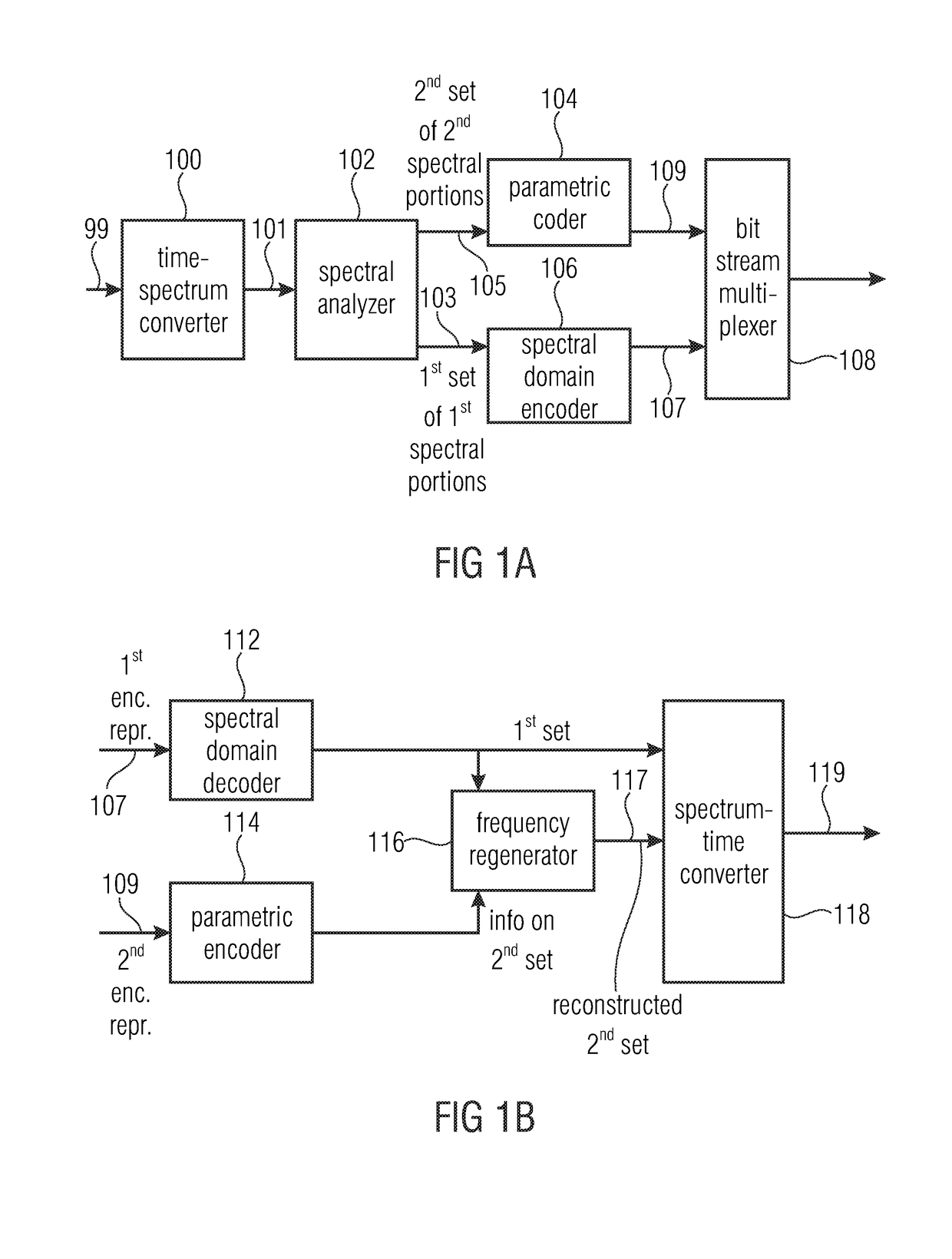
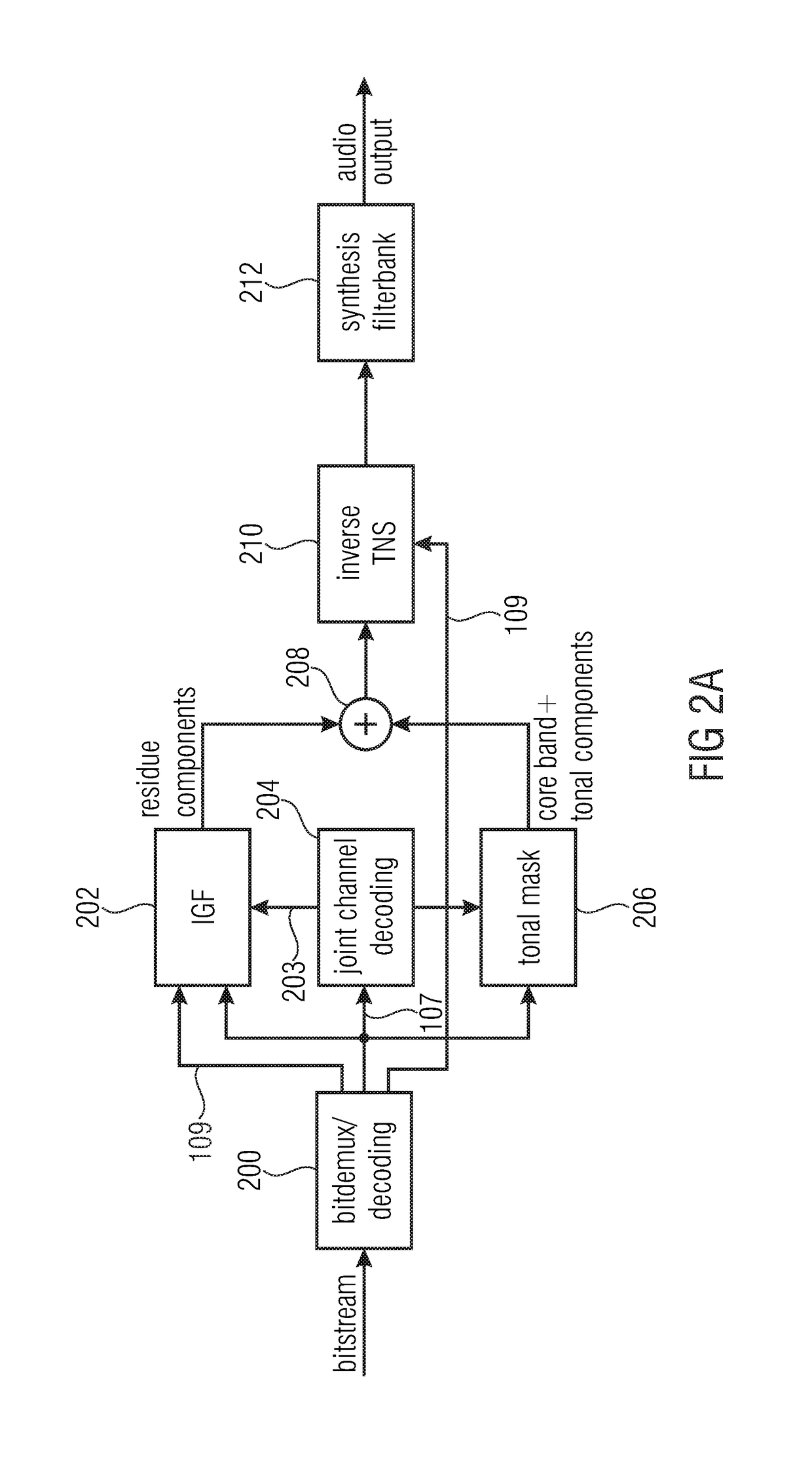
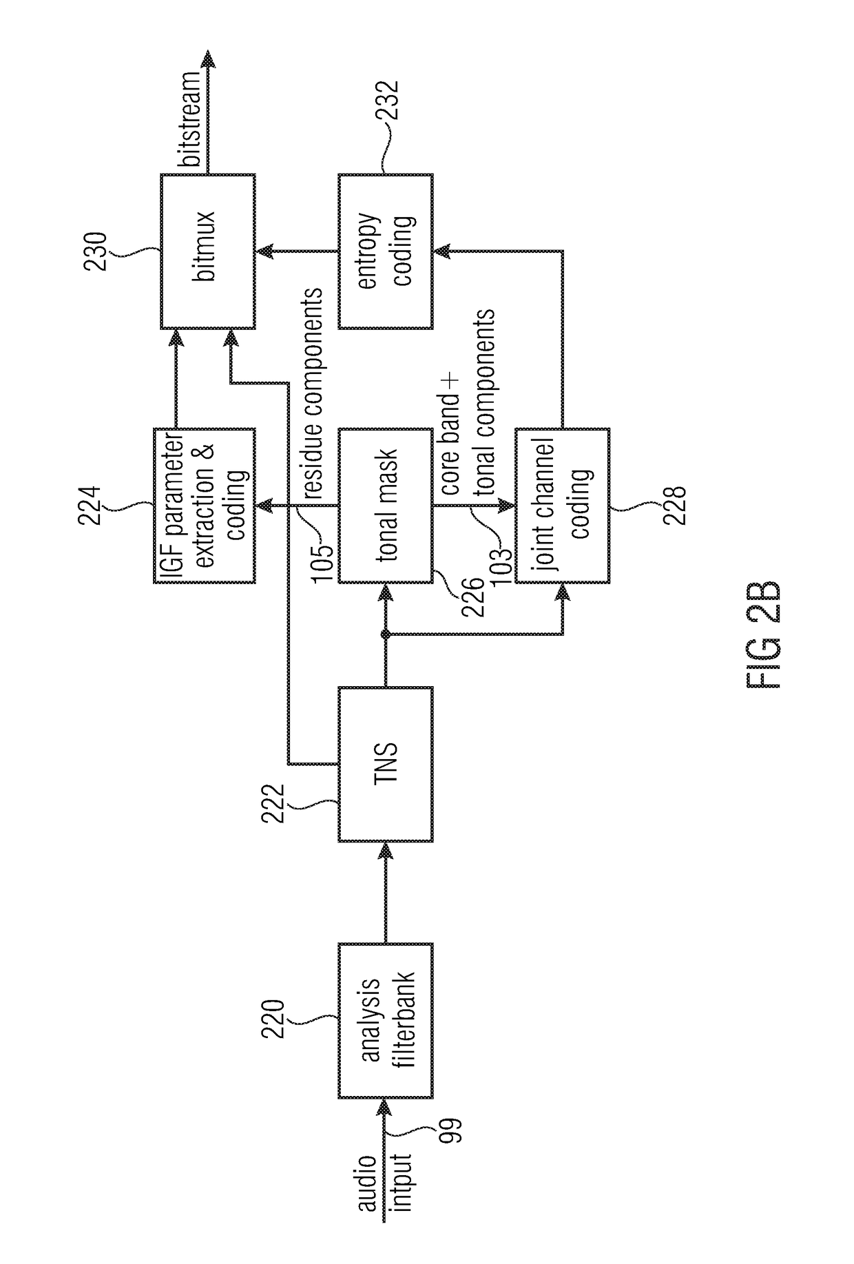
[0086]FIG. 6 illustrates an audio encoder for encoding an audio signal comprising a first encoding processor 600 for encoding a first audio signal portion in a frequency domain. The first encoding processor 600 comprises a time frequency converter 602 for converting the first input audio signal portion into a frequency domain representation having spectral lines up to a maximum frequency of the input signal. Furthermore, the first encoding processor 600 comprises an analyzer 604 for analyzing the frequency domain representation up to the maximum frequency to determine first spectral regions to be encoded with a first spectral representation and to determine second spectral regions to be encoded with a second spectral resolution being lower than the first spectral resolution. In particular, the full-band analyzer 604 determines which frequency lines or spectral values in the time frequency converter spectrum are to be encoded spectral-line wise and which other spectral portions are t...


PUM


Abstract

An audio encoder for encoding an audio signal, includes: a first encoding processor for encoding a first audio signal portion in a frequency domain, wherein the first encoding processor includes: a time frequency converter for converting the first audio signal portion into a frequency domain representation having spectral lines up to a maximum frequency of the first audio signal portion; a spectral encoder for encoding the frequency domain representation; a second encoding processor for encoding a second different audio signal portion in the time domain; a cross-processor for calculating, from the encoded spectral representation of the first audio signal portion, initialization data of the second encoding processor, so that the second encoding processing is initialized to encode the second audio signal portion immediately following the first audio signal portion in time in the audio signal.

Description

CROSS-REFERENCE TO RELATED APPLICATIONS[0001]This application is a continuation of co-pending International Application No. PCT / EP2015 / 067005, filed Jul. 24, 2015, which is incorporated herein by reference in its entirety, and additionally claims priority from European Application No. EP 14 178 819.0, filed Jul. 28, 2014, which is incorporated herein by reference in its entirety.BACKGROUND OF THE INVENTION[0002]The present invention relates to audio signal encoding and decoding and, in particular, to audio signal processing using parallel frequency domain and time domain encoder / decoder processors.[0003]The perceptual coding of audio signals for the purpose of data reduction for efficient storage or transmission of these signals is a widely used practice. In particular when lowest bit rates are to be achieved, the employed coding leads to a reduction of audio quality that often is primarily caused by a limitation at the encoder side of the audio signal bandwidth to be transmitted. H...

Claims


Application Information

Patent Timeline
Patent Type & Authority Patents(United States)
IPC IPC(8): G10L19/02G10L19/18G10L19/22G10L19/24G10L19/022G10L19/26G10L19/083G10L21/038G10L19/04G10L19/028G10L19/00
CPCG10L19/0208G10L19/022G10L19/18G10L19/24G10L19/02G10L2019/0001G10L19/04G10L19/083G10L19/26G10L21/038G10L19/028
Inventor DISCH, SASCHADIETZ, MARTINMULTRUS, MARKUSFUCHS, GUILLAUMERAVELLI, EMMANUELNEUSINGER, MATTHIASSCHNELL, MARKUSSCHUBERT, BENJAMINGRILL, BERNHARD
Owner FRAUNHOFER GESELLSCHAFT ZUR FOERDERUNG DER ANGEWANDTEN FORSCHUNG EV
Why Eureka
Try Eureka