Supercharge Your Innovation With Domain-Expert AI Agents!

Aspirating face seal assembly for a rotary machine

a technology of sealing assembly and rotary machine, which is applied in the direction of engine sealing, machine/engine, engine fuction, etc., can solve the problems of lowering the operating efficiency of rotary machines

Active Publication Date: 2020-05-28
GENERAL ELECTRIC CO
View PDF31 Cites 0 Cited by
  • Summary
  • Abstract
  • Description
  • Claims
  • Application Information

AI Technical Summary

Benefits of technology

This patent describes a seal assembly used in a rotary machine. It consists of a seal bearing and a slide device which helps regulate air pressure within the machine. The seal bearing has an uneven surface that creates areas of low pressure when the parts rotate against each other. These areas help prevent leaks and reduce friction while maintaining a tight seal. Overall, this design improves performance and efficiency of the rotary machines by reducing energy consumption and wear on components.

Problems solved by technology

The technical problem addressed in this patent is how to improve seals between the moving and stationary parts of rotary machines to prevent leaks that would decrease their operational efficiency.

Method used


Image

  • Aspirating face seal assembly for a rotary machine
  • Aspirating face seal assembly for a rotary machine
  • Aspirating face seal assembly for a rotary machine

Examples


Embodiment Construction

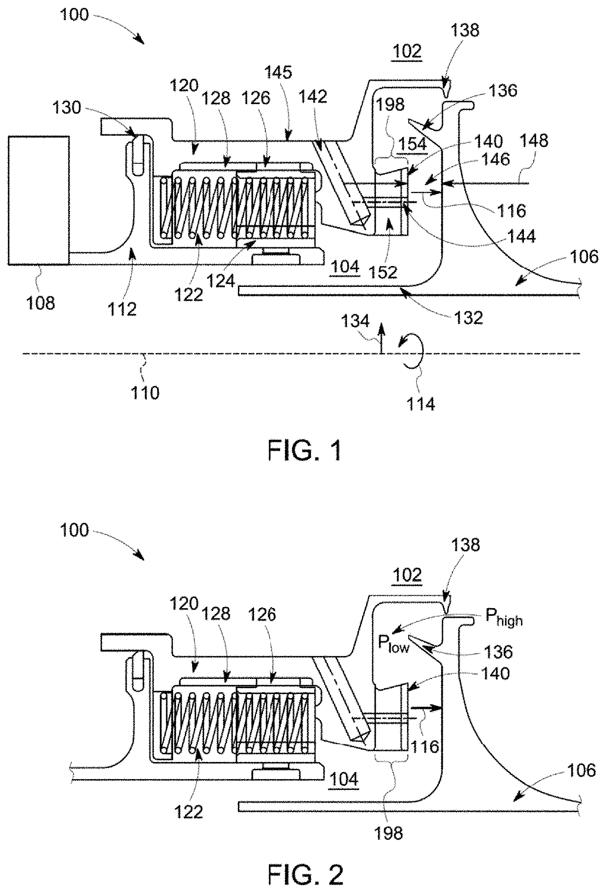
[0034]One or more embodiments of the inventive subject matter described herein provide seal assemblies for rotary machines. The seal assemblies are film-riding hybrid aerostatic-aerodynamic seals for sealing rotor-stator circumferential gaps in gas turbines, steam turbines, aircraft engines, supercritical CO2 turbines, centrifugal compressors, and other rotary machinery. As used herein, the terms “aerostatic” and “aerodynamic” are used to refer to the types of load-bearing pressures in a fluid film formed between the seal assembly and a rotor. The aerostatic forces are fluid film forces created due to pressurization and are thus pressure-dependent in nature. The aerodynamic forces are forces in the fluid film that are dependent on the speed at which the rotor rotates. The term “aero” or fluid should not restrict all embodiments of the inventive subject matter described herein to air as the working fluid. The seal assemblies can operate with other working fluids such as nitrogen, hyd...


PUM


Abstract

A seal assembly for a rotary machine is positioned between a rotating component and a stationary component of the rotary machine. The seal assembly includes a seal bearing face that opposes the rotating component and a slide device. The slide device is positioned between different fluid pressure volumes in the rotary machine. The slide device axially moves toward the rotating component responsive to pressurization of the rotary machine. The slide device includes cross-over ports and the seal bearing face includes feed ports. The feed ports extend through the seal bearing face to form an aerostatic portion of a film bearing between the seal bearing face and the rotating component. The seal bearing face and/or the rotating component is a non-planar surface that, during rotating motion of the rotating component, forms an aerodynamic portion of the film bearing between the seal bearing face and the rotating component.

Description


Claims


Application Information

Patent Timeline
Owner GENERAL ELECTRIC CO
Features
  • R&D
  • Intellectual Property
  • Life Sciences
  • Materials
  • Tech Scout
  • Unparalleled Data Quality
  • Higher Quality Content
  • 60% Fewer Hallucinations
Learn More