
Vial inspection method and apparatus

a technology of glass vials and inspection methods, applied in the field of inspection systems, can solve the problems of small cracks or fissures that may develop in the glass vials, defects that are often present in the heel of the vial, and are difficult to d

Active Publication Date: 2020-06-04
F HOFFMANN LA ROCHE & CO AG
View PDF8 Cites 0 Cited by
  • Summary
  • Abstract
  • Description
  • Claims
  • Application Information

AI Technical Summary

Benefits of technology

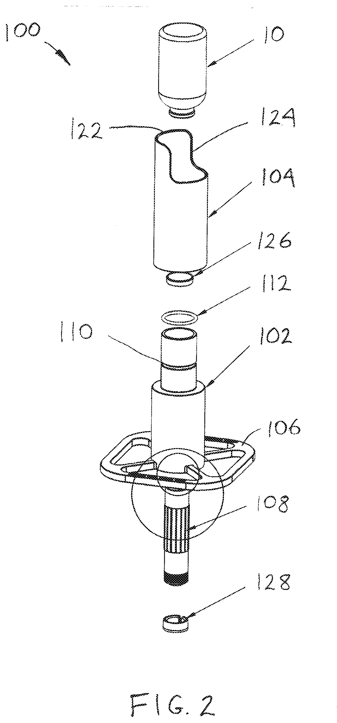
The present patent relates to a system and method for inspecting glass vials. The system includes a stand with an illumination and inspection system. The stand has a cavity for holding a light source and a recess for holding a vial. The stand aims the light source towards the vial, which interacts with defects and makes them more visible. The stand can position vials for inspection by an inspector. The light source is a flashlight and the stand can hold various types of vials and retain them in a vertical orientation. The stand may also have a bottom lid to retain the light source. The method involves inserting the vial into the stand and inspecting it for defects while spinning it. Overall, the system and method facilitate efficient inspection of glass vials.

Problems solved by technology

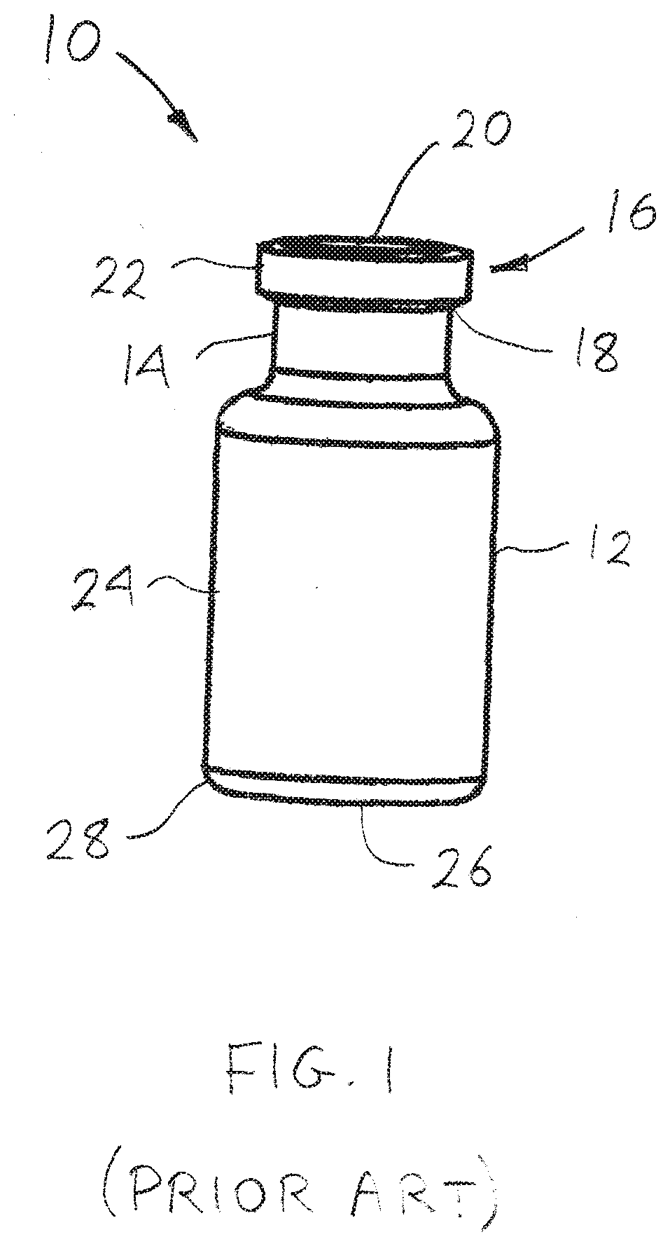
Small cracks or fissures may develop in the glass vials, either before or during the vial filling process.
These defects often occur in the heel of the vial (i.e. its outer, bottom edge) or just beneath the neck where the cap attaches to the top of the vial.
These defects can be difficult to detect and can compromise the integrity of the vial and / or its contents.
For example, medicine may leak from the vial through the crack.
Air, moisture or other contaminants may enter the vial through the crack and contaminate the medicine.
A fissure may propagate into a larger crack and cause the vial to break open.

Method used


Image

  • Vial inspection method and apparatus
  • Vial inspection method and apparatus
  • Vial inspection method and apparatus

Examples


Embodiment Construction

[0027]Before the present invention is further described, it is to be understood that this disclosure is not limited to particular embodiments described, as such may, of course, vary. It is also to be understood that the terminology used herein is for the purpose of describing particular embodiments only, and is not intended to be limiting, since the scope of the present disclosure will be limited only by the appended claims.

[0028]Where a range of values is provided, it is understood that each intervening value, to the tenth of the unit of the lower limit unless the context clearly dictates otherwise, between the upper and lower limit of that range and any other stated or intervening value in that stated range, is encompassed within the invention. The upper and lower limits of these smaller ranges may independently be included in the smaller ranges, and are also encompassed within the invention, subject to any specifically excluded limit in the stated range. Where the stated range in...


PUM


Abstract

A glass vial illumination and inspection system may be provided with a light source and a stand. The stand may have an internal cavity configured to receive at least a portion of the light source. A recess may be located in the stand and configured to receive at least a portion of a glass vial. The stand may be configured to aim the light output from the light source toward the glass vial to illuminate the vial. The stand may be configured to position the vial such that an inspector can manually inspect the illuminated vial for defects. Methods of use are also disclosed.

Description

CROSS REFERENCE TO RELATED APPLICATIONS[0001]This application claims the benefit of U.S. Provisional Application Ser. No. 62 / 773,985 filed Nov. 30, 2018, and U.S. Provisional Application Ser. No. 62 / 837,521 filed Apr. 23, 2019, each of which are herein incorporated by reference in its entirety.INCORPORATION BY REFERENCE[0002]All publications and patent applications mentioned in this specification are incorporated herein by reference in their entirety to the same extent as if each individual publication or patent application was specifically and individually indicated to be incorporated by reference.FIELD[0003]The present disclosure relates to inspection systems, in particular to systems and methods for inspecting glass vials.BACKGROUND[0004]Various products such as medicines are provided in glass vials. Medicines are often provided in a liquid or lyophilized form. Small cracks or fissures may develop in the glass vials, either before or during the vial filling process. These defects...

Claims


Application Information

Patent Timeline
IPC IPC(8): G01N21/15
CPCG01N21/15G01N2021/157G01N21/8803G01N21/9009
Inventor COLES, NICHOLASGESSFORD, MAKAYLANORRISS, ANDREW DAVIDSHIRASAKI, MITSUTAKA
Owner F HOFFMANN LA ROCHE & CO AG
Learn More