Dental attachment placement structure

a technology for placing structures and teeth, applied in dental surgery, othrodontics, medical science, etc., can solve problems such as difficulty in application by orthodontic practitioners, and achieve the effect of enhancing optical diffusivity and facilitating light diffusion

Pending Publication Date: 2020-06-18
ALIGN TECH
View PDF2 Cites 18 Cited by
  • Summary
  • Abstract
  • Description
  • Claims
  • Application Information

AI Technical Summary

Benefits of technology

[0026]As mentioned, the bonding surface may be configured as an optical diffuser to diffuse a wavelength of light that cross-links a bonding agent on the bonding surface of the device. The diffuser may generally spread out (more evenly diffuse) light passing through the bonding surface, and may be configured as a holograph

Problems solved by technology

In some cases multiple attachments may be used on the teeth, wh

Method used


Image

  • Dental attachment placement structure
  • Dental attachment placement structure
  • Dental attachment placement structure

Examples


Embodiment Construction

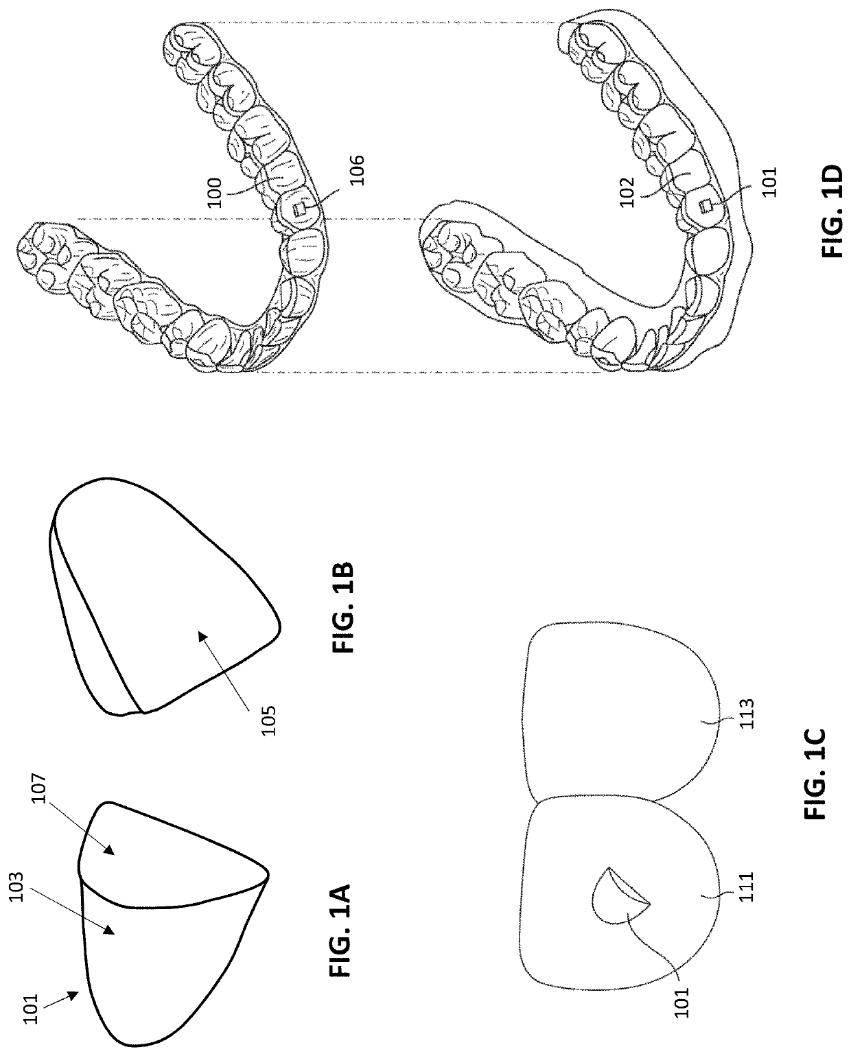
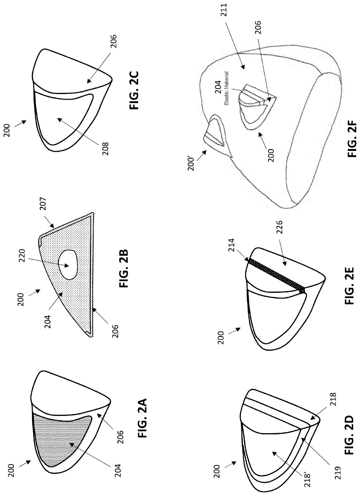
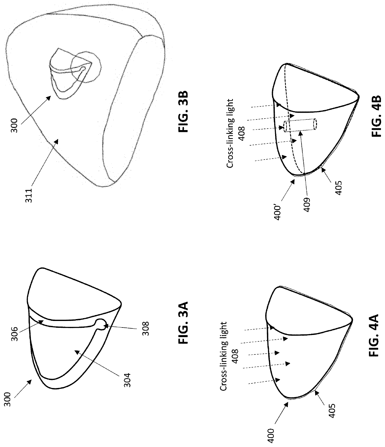
[0053]In general, described herein are orthodontic attachment devices for interacting with an orthodontic appliance, as well as systems include any of these orthodontic attachment devices, methods of forming the orthodontic attachment devices, and / or methods of using the orthodontic attachment devices to adjust a patient's dentition. An orthodontic attachment devices may also be referred to as an orthodontic attachment or simply an attachment.

[0054]Any of the orthodontic attachment devices may include an anchoring attachment body, a bonding surface on the anchoring attachment body, said bonding surface configured for anchoring the anchoring attachment body to a tooth; and an orthodontic appliance engagement surface on the anchoring attachment body. The orthodontic appliance engagement surface may be configured to contact the orthodontic appliance and apply a locking force between the anchoring attachment body and the orthodontic appliance when the orthodontic appliance engages the o...


PUM


Abstract

Orthodontic attachment devices for interacting with an orthodontic appliance are described. Described herein are orthodontic attachment devices that include one or more features to improve the bonding to the teeth, improve the appearance of the orthodontic attachment device, improve the transfer of force from the orthodontic appliance to the tooth/teeth, improve the connection between the orthodontic attachment device and the orthodontic appliance, improve the ease and ability of removal of the appliance from the teeth, reduce the weight of the orthodontic attachment device, increase the stability of the connection of the orthodontic attachment device on the tooth, and/or reduce the number of steps for applying the orthodontic attachment device to the patient's teeth.

Description

CROSS REFERENCE TO RELATED APPLICATIONS[0001]This application claims the benefit of U.S. Provisional Patent Application No. 62 / 778,827, filed Dec. 12, 2018, titled “DENTAL ATTACHMENT PLACEMENT STRUCTURE,” which is herein incorporated by reference in its entirety.INCORPORATION BY REFERENCE[0002]All publications and patent applications mentioned in this specification are herein incorporated by reference in their entirety to the same extent as if each individual publication or patent application was specifically and individually indicated to be incorporated by reference.[0003]In particular, U.S. Pat. No. 8,562,337, and U.S. patent application publications no. 2017 / 0319296, and 2017 / 0231722 are herein incorporate by reference in their entirety.FIELD[0004]Described herein are orthodontic appliance attachments, and specifically orthodontic appliance attachment devices that bind to the patient's tooth or teeth and interact with a dental appliance (such as a polymeric shell dental appliance...

Claims


Application Information

Patent Timeline
IPC IPC(8): A61C7/16A61C7/08
CPCA61C7/08A61C7/16A61C7/14
Inventor KOPELMAN, AVILI, CHUNHUA
Owner ALIGN TECH
Why Eureka
Try Eureka