Gas without vent for patient interface

a patient interface and gas technology, applied in the field of gas without vent for patient interface, can solve the problems of csr harmful, cardiovascular disease and brain damage, excessive daytime somnolence, etc., and achieve the effects of improving comfort, cost, efficacy, and ease of us

Active Publication Date: 2020-06-18
RESMED LTD
View PDF0 Cites 0 Cited by
  • Summary
  • Abstract
  • Description
  • Claims
  • Application Information

AI Technical Summary

Benefits of technology

[0045]Delivery of a flow of air without humidification may cause drying of airways. The use of a humidifier with an RPT device and the patient interface produces humidified gas that minimizes drying of the nasal mucosa and increases patient airway comfort. In addition in cooler climates, warm air applied generally to the face area in and about the patient interface is more comfortable than cold air. A range of artificial humidification devices and systems are known, however they may not fulfil the specialised requirements of a medical humidifier.
[0048]The present technology is directed towards providing medical devices used in the diagnosis, amelioration, treatment, or prevention of respiratory disorders having one or more of improved comfort, cost, efficacy, ease of use and manufacturability.
[0051]An aspect of certain forms of the present technology is to provide methods and / or apparatus that improve the compliance of patients with respiratory therapy.
[0052]One form of the present technology comprises a gas washout vent with at least one outlet orifice; a diffusing member covering the outlet orifice; and a blocking member having an air-impermeable material, the blocking member preventing gas exiting from the outlet orifice from flowing straight through the diffusing member.
[0053]Another aspect of one form of the present technology is a patient interface for sealed delivery of a flow of air at a continuously positive pressure with respect to ambient air pressure to an entrance to the patient's airways including at least an entrance of a patient's nares, wherein the patient interface is configured to maintain a therapy pressure in a range of about 4 cmH2O to about 30 cmH2O above ambient air pressure in use, throughout the patient's respiratory cycle, while the patient is sleeping, to ameliorate sleep disordered breathing, the patient interface comprising: a sealing structure configured to seal around the entrance to the patient's airways; a positioning and stabilising structure to maintain the sealing structure in sealing contact with an area surrounding the entrance to the patient's airways while maintaining a therapeutic pressure at the entrance to the patient's airways; a plenum chamber configured to be pressurised at a pressure above ambient pressure in use; a gas washout vent configured to allow patient-exhaled CO2 to flow to an exterior of the plenum chamber to minimise rebreathing of exhaled CO2 by the patient, the gas washout vent including at least one outlet orifice; a diffusing member at least partly covering the outlet orifice; and a blocking member having an air-impermeable material, the blocking member preventing gas exiting from the outlet orifice from flowing straight through the diffusing member.

Problems solved by technology

It often causes excessive daytime somnolence, and it may cause cardiovascular disease and brain damage.
It is possible that CSR is harmful because of the repetitive hypoxia.
In some patients CSR is associated with repetitive arousal from sleep, which causes severe sleep disruption, increased sympathetic activity, and increased afterload.
Symptoms include dyspnea, morning headache and excessive daytime sleepiness.
Some NMD patients are characterised by progressive muscular impairment leading to loss of ambulation, being wheelchair-bound, swallowing difficulties, respiratory muscle weakness and, eventually, death from respiratory failure.
Symptoms of respiratory failure in NMD include: increasing generalised weakness, dysphagia, dyspnea on exertion and at rest, fatigue, sleepiness, morning headache, and difficulties with concentration and mood changes.
Chest wall disorders are a group of thoracic deformities that result in inefficient coupling between the respiratory muscles and the thoracic cage.
Scoliosis and / or kyphoscoliosis may cause severe respiratory failure.
Symptoms of respiratory failure include: dyspnea on exertion, peripheral oedema, orthopnea, repeated chest infections, morning headaches, fatigue, poor sleep quality and loss of appetite.
Treatment of OSA by CPAP therapy may be voluntary, and hence patients may elect not to comply with therapy if they find devices used to provide such therapy one or more of: uncomfortable, difficult to use, expensive and aesthetically unappealing.
For other forms of therapy, such as the delivery of oxygen, the patient interface may not include a seal sufficient to facilitate delivery to the airways of a supply of gas at a positive pressure of about 10 cmH2O.
The design of a patient interface presents a number of challenges.
As a consequence of these challenges, some masks suffer from being one or more of obtrusive, aesthetically undesirable, costly, poorly fitting, difficult to use, and uncomfortable especially when worn for long periods of time or when a patient is unfamiliar with a system.
For example, masks designed solely for aviators, masks designed as part of personal protection equipment (e.g. filter masks), SCUBA masks, or for the administration of anaesthetics may be tolerable for their original application, but nevertheless such masks may be undesirably uncomfortable to be worn for extended periods of time, e.g., several hours.
This discomfort may lead to a reduction in patient compliance with therapy.
If a mask is uncomfortable, or difficult to use a patient may not comply with therapy.
Since it is often recommended that a patient regularly wash their mask, if a mask is difficult to clean (e.g., difficult to assemble or disassemble), patients may not clean their mask and this may impact on patient compliance.
A seal-forming portion that may be effective in one region of a patient's face may be inappropriate in another region, e.g., because of the different shape, structure, variability and sensitivity regions of the patient's face.
For example, a seal on swimming goggles that overlays a patient's forehead may not be appropriate to use on a patient's nose.
Like the previous style of seal forming portion, if the match between the face and the mask is not good, additional force may be required to achieve a seal, or the mask may leak.
Furthermore, if the shape of the seal-forming portion does not match that of the patient, it may crease or buckle in use, giving rise to leaks.
Another type of seal-forming portion may comprise a friction-fit element, e.g., for insertion into a naris, however some patients find these uncomfortable.
Some patients may find it inconvenient to constantly apply and remove an adhesive to their face.
However, the use of adhesives may be uncomfortable for some.
Many such harnesses suffer from being one or more of ill-fitting, bulky, uncomfortable and awkward to use.
Many such vents are noisy.
Others may become blocked in use and thus provide insufficient washout.
However, air pressure generators for medical applications have particular requirements not fulfilled by more generalised air pressure generators, such as the reliability, size and weight requirements of medical devices.
In addition, even devices designed for medical treatment may suffer from shortcomings, pertaining to one or more of: comfort, noise, ease of use, efficacy, size, weight, manufacturability, cost, and reliability.
An example of the special requirements of certain RPT devices is acoustic noise.
Delivery of a flow of air without humidification may cause drying of airways.
A range of artificial humidification devices and systems are known, however they may not fulfil the specialised requirements of a medical humidifier.
Room-based systems (e.g. a sauna, an air conditioner, or an evaporative cooler), for example, may also humidify air that is breathed in by the patient, however those systems would also humidify and / or heat the entire room, which may cause discomfort to the occupants.
Furthermore medical humidifiers may have more stringent safety constraints than industrial humidifiers
Some medical humidifiers may provide inadequate humidification, some are difficult or inconvenient to use by patients.

Method used


Image

  • Gas without vent for patient interface
  • Gas without vent for patient interface
  • Gas without vent for patient interface

Examples


Embodiment Construction

[0100]Before the present technology is described in further detail, it is to be understood that the technology is not limited to the particular examples described herein, which may vary. It is also to be understood that the terminology used in this disclosure is for the purpose of describing only the particular examples discussed herein, and is not intended to be limiting.

[0101]The following description is provided in relation to various examples which may share one or more common characteristics and / or features. It is to be understood that one or more features of any one example may be combinable with one or more features of another example or other examples. In addition, any single feature or combination of features in any of the examples may constitute a further example.

4.1 Therapy

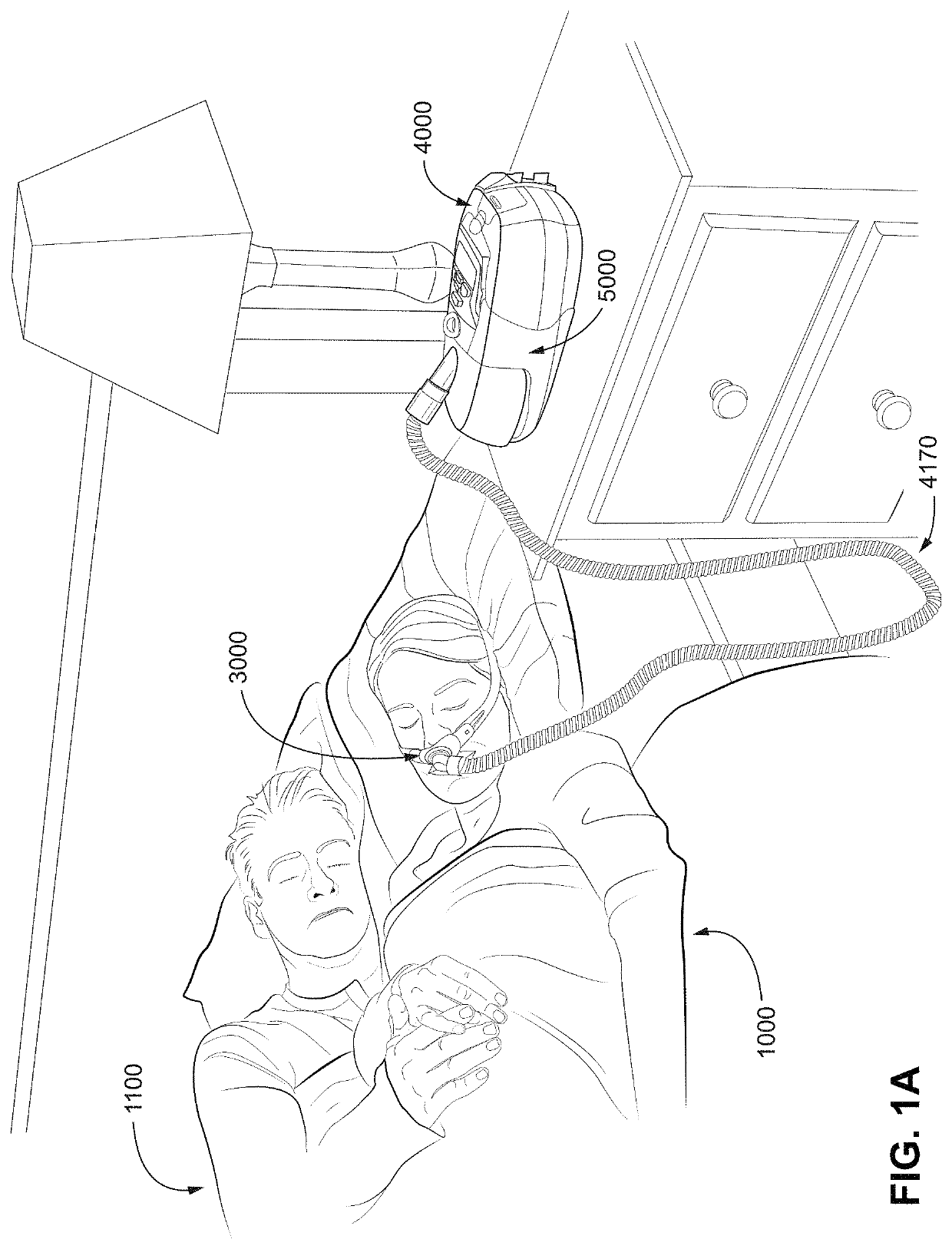
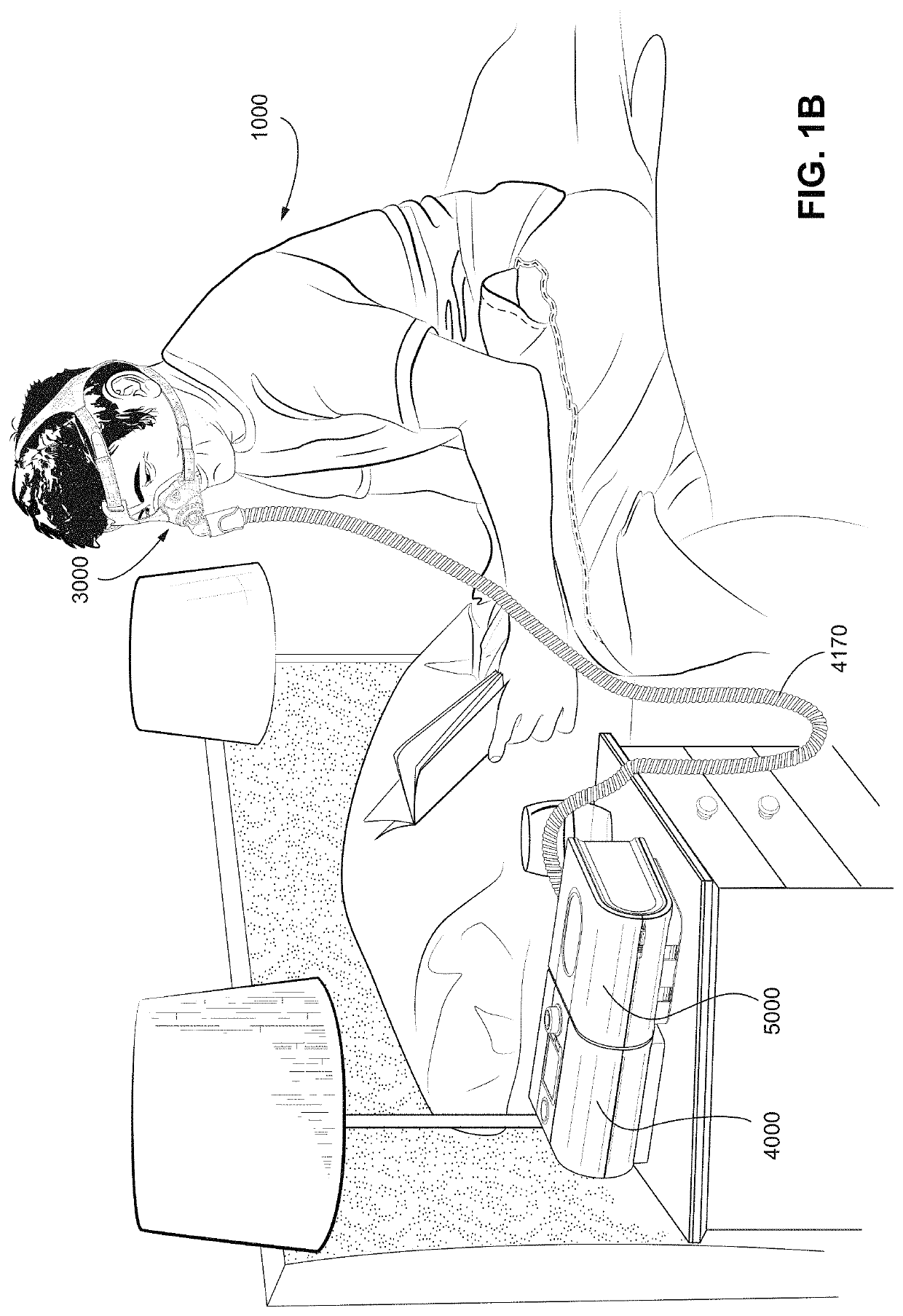
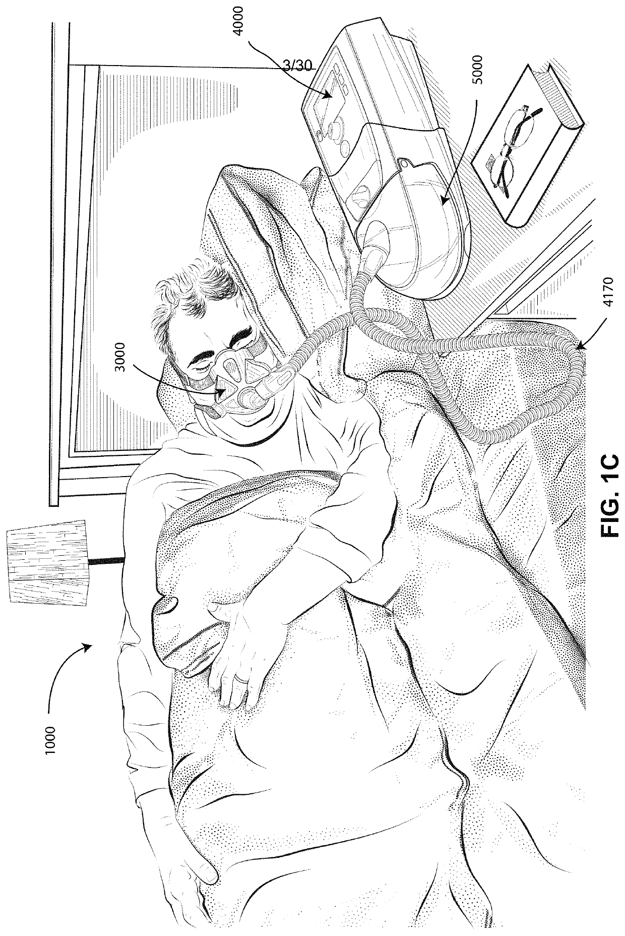
[0102]In one form, the present technology comprises a method for treating a respiratory disorder comprising the step of applying positive pressure to the entrance of the airways of a patient 1000.

[0103]...


PUM


Abstract

A gas washout vent, and a patient interface with the gas washout vent, configured to allow patient-exhaled CO2 to flow to an exterior of the plenum chamber to minimise rebreathing of exhaled CO2 by the patient, the gas washout vent including at least one outlet orifice; a diffusing member at least partly covering the outlet orifice; and a blocking member having an air-impermeable material, the blocking member preventing gas exiting from the outlet orifice from flowing straight through the diffusing member.

Description

CROSS REFERENCE TO RELATED APPLICATIONS[0001]This application is a continuation application of U.S. patent application Ser. No. 15 / 512,149, filed 17 Mar. 2017, which is the U.S. national phase of International Application No. PCT / AU2015 / 050560 filed 18 Sep. 2015, which designated the U.S. and claims priority to U.S. Provisional Application No. 62 / 141,342, filed 1 Apr. 2015 and AU Provisional Application No. 2014903730, filed 18 Sep. 2014, the entire contents of each of which are hereby incorporated by reference in their entirety.[0002]A portion of the disclosure of this patent document contains material which is subject to copyright protection. The copyright owner has no objection to the facsimile reproduction by anyone of the patent document or the patent disclosure, as it appears in Patent Office patent files or records, but otherwise reserves all copyright rights whatsoever.BACKGROUND OF THE TECHNOLOGY1.1 Field of the Technology[0003]The present technology relates to one or more ...

Claims


Application Information

Patent Timeline
Patent Type & Authority Applications(United States)
IPC IPC(8): A61M16/22A61M16/06A61M16/08
CPCA61M16/0622A61M16/0816A61M16/0616A61M16/22A61M16/06A61M2202/0225A61M2205/42A61M16/0683A61M16/0825A61M16/0666A61M2202/0085
Inventor DANTANARAYANA, MUDITHA PRADEEP
Owner RESMED LTD
Why Eureka
Try Eureka